Superposition
Introduction: This article covers the topic of superposition approach in circuit analysis.
The Essentials
A method of circuit analysis is called superposition. Superposition states that when more than one independent source of energy is present, the response of the circuit is the sum of individuals responses.
Using a circuit schematic may help us in understanding superposition

Figure 1: Superposition Circuit
Here we have a circuit with two independent power sources, a voltage and current source. By the principle of superposition, both power sources create a unique response in each element of the circuit. Since the resistors have a linear relationship, we can do this without breaking any rules.
When it comes to using superposition, follow these steps; 1) "cover-up" or "remove" one source from the circuit, 2) analyze the individual response of the elements from the remaining power source (voltage, current, etc.), 3) repeat the process but cover up the other source, and finally, 4) add the individual responses over the elements to get the total response of each element.
To understand this further, we will show the circuit above when we "cover up" the given power sources. Figures 2. and 3. show both instances of both sources being covered up individually.

Figure 2: Superposition Circuit (Current Source Covered)

Figure 3: Superposition Circuit (Voltage Source Covered)
You will notice in Figure 2. that when we cover the current source up, it will leave an open circuit portion while in Figure 3. there is a wire instead. This is how we are to analyze the circuits whenever we use superposition. When we cover a voltage source, we replace it with a wire. When we cover a current source, we replace it with an open circuit.
From this, we analyze both variations of the circuit as you would analyze a circuit normally. Keep track of values you are expecting to calculate. For example, if you are curious about the current through R3, calculate the current through R3 in both circuit variations and at the end add them up. The textbook you use also use the notation of calculating \( i_{R3} = i'_{R3} + i''_{R3} \), where \( i' \) is the current of one circuit variation and \( i'' \) is the current of the other.
Doing an example may help solidify this concept.
Example
Let's use the same circuit as the essentials section but attach some values to it.

Figure 4: Superposition Example
Let's say for this problem we are curious to find the current through all resistors. Now let's go through step by step.
First step, cover up one source. You can cover up any of the two sources, but for this example let's cover up the current source. Figure 5. has the first variation of this circuit.
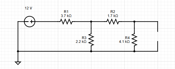
Figure 5: Superposition Example Variation 1
Now let's analyze the circuit, finding the current through each resistor. We can do this by using mesh analysis to find the current.
After using mesh analysis, we get these current values.
\[ i'_1 = 2.266 \, \text{mA}\] \[ i'_2 = 0.623 \, \text{mA}\] \[i'_3 = 1.643 \, \text{mA}\] \[ i'_4 = 0.623 \, \text{mA}\]
Remember that the last branch with R2 and R4 have the same current due to the open circuit situated where the current source used to be. Charges do not flow when there is a break in the circuit. so the current through R2 is the same as the current through R4.
Now let's analyze the circuit in its other variation, where the voltage source is covered.

Figure 6: Superposition Example Variation 2
Now let's do mesh analysis to analyze the unique currents through the resistors from this current source.
Once done correctly, we should get these values;
\[ i''_1 = -0.42 \, \text{mA}\] \[ i''_2 = -1.14 \, \text{mA}\] \[ i''_3 = 0.72 \, \text{mA}\] \[ i''_4 = 0.86 \, \text{mA}\]
One thing to mention is the negative currents, namely \( i''_1 \, \text{and} \, i''_2 \). This is because we kept the same mesh current direction as the previous analysis. This is crucial so that when we sum the currents in the end, they will equal the correct current through each resistor in the circuit.
Finally, let's sum the currents of each variation of the circuit.
\[ i_1 = i'_1 + i''_1 = 2.266 + (-0.42) = 1.846 \, \text{mA}\]
\[ i_2 = i'_2 + i''_2 = 0.623 + (-1.14) = -0.517 \, \text{mA}\]
\[ i_3 = i'_3 + i''_3 = 1.643 + 0.72 = 2.363 \, \text{mA}\]
\[ i_4 = i'_4 + i''_4 = 0.623 + 0.86 = 1.483 \, \text{mA}\]
Each of these currents, \( i_1 \) through \( i_4 \), are the currents through each resistor. \( i_2 \) is described as negative because we assumed the current is going clockwise in that mesh, but the current goes in the other direction.
Practice
Problem 1.) Using Figure 7., find the node voltages using superposition analysis.
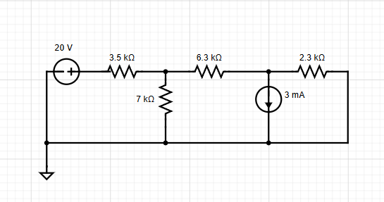
Figure 7: Problem 1
Problem 2.) Using Figure 8., find the current through each resistor using superposition analysis.
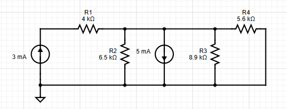
Figure 8: Problem 2
Problem 3.) Using Figure 9., find the voltage at each node using superposition.
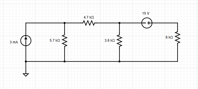
Figure 9: Problem 3
Problem 4.) Using Figure 10., find the current through each resistor using superposition.
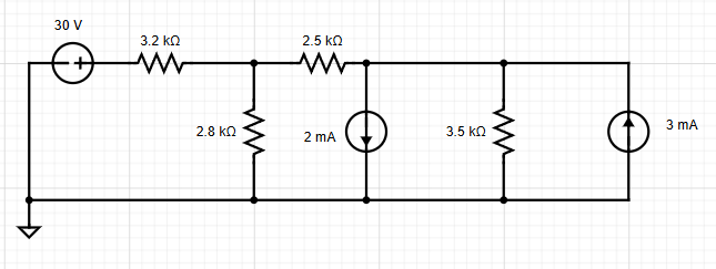
Figure 10: Problem 4
Solutions:
Problem 1 Solution.) \( V_A = 9.02 \, \text{V} \) and \( V_B = -2.64 \, \text{V} \). Let's first cover up the current source. That will act like a open circuit so no flow of current happens in that branch.
Doing nodal analysis, we find the following:
\[ V_A' = 10.49 \, \text{V}\] \[V_B' = 2.8 \, \text{V}\]
These voltages are for the first iteration, now let's calculate the node voltages for the second iteration.
As we cover up the voltage source, it is replaced with a wire. Now we can analyze the circuit once again.
\[ V''_A = -1.47 \, \text{V}\] \[V''_B = -5.45 \, \text{V}\]
Now we sum these voltages to get the with their other iteration of voltages to get the final answer.
\[ V_A = V'_A + V''_A = 9.02 \, \text{V}\]
\[ V_B = V'_B + V''_B = -2.64 \, \text{V}\]
Problem 2 Solution.) \( i_{R1} = 3 \, \text{mA} \), \( i_{R2} = 0.689\, \text{mA} \), \( i_{R3} = 0.51 \, \text{mA} \), and \( i_{R4} = 0.8 \, \text{mA} \). Let's begin by replacing the 3 mA source with an open circuit and analyze the circuit using mesh analysis. For this circumstance, there are two branches that share the same current source, the 5 mA source. We use supermesh analysis for this circumstance and we get the following current values.
\[ i_1' = 1.73 \, \text{mA}\] \[ i_2' = -3.27 \, \text{mA}\] \[ i_3' = -2 \, \text{mA}\]
From this we can find the current through each resistor. We solve this using the logic found below:
\[ i_{R2}' = 1.729 \, \text{mA}\] \[ i_{R3}' = i_2' - i_3' = -1.27 \, \text{mA}\] \[ i_{R4}' = -2\, \text{mA} \]
Now notice, since \( R_4 \) is in series with the open circuit, the current through that resistor is 0 mA. Thus, after all of this analysis, we have the following values:
\[ i_{R1}' = 0 \, \text{mA} \] \[ i_{R2}' = 1.729 \, \text{mA}\] \[ i_{R3}' = -1.27 \, \text{mA}\] \[ i_{R4}' = -2\, \text{mA} \]
Now repeat the process but this time bring back the 3 mA source and replace the 5 mA source with an open circuit. Finding the mesh current in each mesh, we get the following:
\[i_1'' = 3 \, \text{mA}\] \[ i_2'' = 1.96 \, \text{mA}\] \[ i_3'' = 1.2 \, \text{mA}\]
Now using the mesh currents we can solve for the currents through each resistor:
\[ i_{R1}'' = i_1'' = 3 \, \text{mA}\] \[ i_{R2}'' = i_1'' - i_2'' = -1.04 \, \text{mA}\] \[ i_{R3}'' = i_2'' - 1_3'' = 0.76 \, \text{mA}\] \[ i_{R4}'' = i_3'' = 1.2 \, \text{mA}\]
Now with both variations of current through each resistor, we can add both variations.
\[ i_{R1} = i_{R1}' + i_{R1}'' = 3\, \text{mA}\] \[ i_{R2} = i_{R2}' + i_{R2}'' = 0.689 \, \text{mA}\] \[ i_{R3} = i_{R3}' + i_{R3}'' = -0.51 \, \text{mA}\] \[ i_{R4} = i_{R4}' + i_{R4}'' = -0.8 \ \text{mA}\]
Problem 3 Solution.) \( V_A = 7.47 \, \text{V} \), \( V_B = 0.46 \, \text{V} \), and \( V_C = 14.54 \, \text{V} \). First replace the voltage source with a wire and use node voltage analysis.
\[ V_A' = 9.53 \, \text{V}\] \[ V_B' = V_C' = 3.3 V\]
Now let's replace the current source with an open circuit. Note how if we do nodal analysis, we need to use the supernode method due to the voltage source used. Using that method and nodal analysis, we get the following:
\[ V_A'' = -2.06 \, \text{V}\] \[ V_B'' = -3.76 \, \text{V}\] \[ V_C'' = 11.24 \, \text{V}\]
Now we can sum the voltages from both iterations and get the final node voltages.
\[ V_A = V_A' + V_A'' = 7.47 \, \text{V}\] \[ V_B = V_B' + V_B'' = -0.46 \, \text{V}\] \[ V_C = V_C' + V_C'' = 14.54 \, \text{V}\]
Problem 4 Solution.) \( i_{3.2} = 5.65 \, \text{mA} \), \( i_{2.8} = 4.25 \, \text{mA} \), \( i_{2.5} = 1.4 \, \text{mA} \), and \( i_{3.5} = 2.4 \, \text{mA} \). While this circuit involves three separate sources, the same principle applies. So let's replace both current sources with open circuits and analyze the current through these resistors. After using mesh analysis, we can get the following mesh currents:
\[ i_1' = 5.87 \, \text{mA}\] \[ i_2' = i_3' =1.87 \, \text{mA}\]
We can find the current through resistors using the logic of current in branches.
\[i_{3.2}' = i_1' = 5.87 \, \text{mA}\] \[ i_{2.8}' = i_1' - i_2' = 4 \, \text{mA}\] \[ i_{2.5}' = i'_{3.5} = 1.87 \, \text{mA}\]
These currents are for the voltage source turned on. Now let's replace the voltage source with a wire and bring back the 2 mA current source. Remember that this source is shared by two branches, thus we need to use supermesh analysis to find the current in each mesh. Using mesh analysis we find the following:
\[ i_1''= 0.436 \, \text{mA}\] \[ i_2''=0.934 \, \text{mA}\] \[ i_3'' = -1.07 \, \text{mA}\]
Now to calculate the current through resistors.
\[ i_{3.2}'' = i_1'' = 0.436 \, \text{mA}\] \[ i_{2.8}'' = i_1'' - i_2'' = -0.498 \, \text{mA}\] \[ i''_{2.5} = i_2'' = 0.934 \, \text{mA}\] \[ i_{3.5}'' = i_3'' = -1.07 \, \text{mA}\]
Finally, for the last current source. Replace the voltage source with wire and the 2 mA source with an open circuit. Now analyze with mesh current analysis once again.
\[ i_1''' = -0.654 \, \text{mA}\] \[ i_2'''=-1.4 \, \text{mA}\] \[ i_3'''= -3\, \text{mA}\]
Then calculate the current through each resistor:
\[ i_{3.2}'''= i_1''' = -0.654 \, \text{mA}\] \[ i_{2.8}''' = i_1'''-i_2''' = 0.746 \, \text{mA}\] \[ i_{2.5}''' = -1.4 \, \text{mA}\] \[ i_{3.5}''' = i_2''' - i_3''' = 1.6 \, \text{mA}\]
Now the final currents are the sum of all iterations of the current through their respective resistors.
\[ i_{3.2} = i_{3.2}' + i_{3.2}'' + i_{3.2}''' = 5.65 \, \text{mA}\] \[ i_{2.8} = i_{2.8}' + i_{2.8}'' + i_{2.8}''' = 4.25 \, \text{mA}\] \[ i_{2.5} = i_{2.5}' + i_{2.5}'' + i_{2.5}''' = 1.4 \, \text{mA}\] \[ i_{3.5} = i_{3.5}' + i_{3.5}'' + i_{3.5}''' = 2.4 \, \text{mA}\]