
Shear Strain and Stress and Design
Shear Stress
Shear Stress is a stress that acts tangential to the surface of a material.
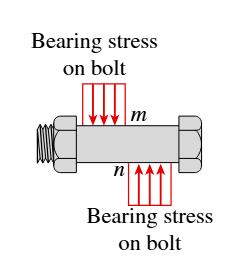
Bearing Stress
Bearing stresses are contact stresses that develop under tensile loads between connections.
where the bearing area is the projected area of the bearing surface.
Single Shear vs. Double Shear
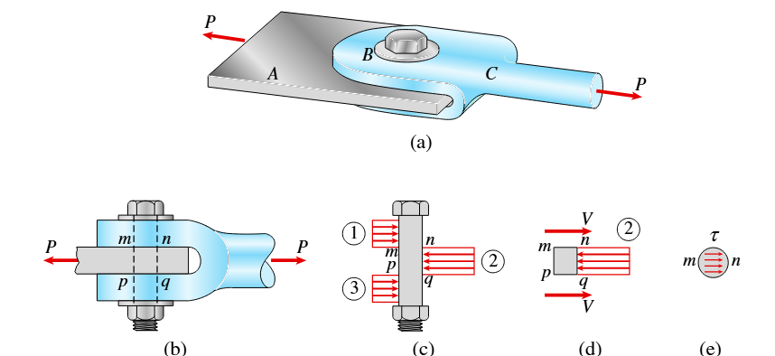
|
Single Shear: The axial load (P) is cut across one plane of shear. |
|
|---|---|
Shear Strain
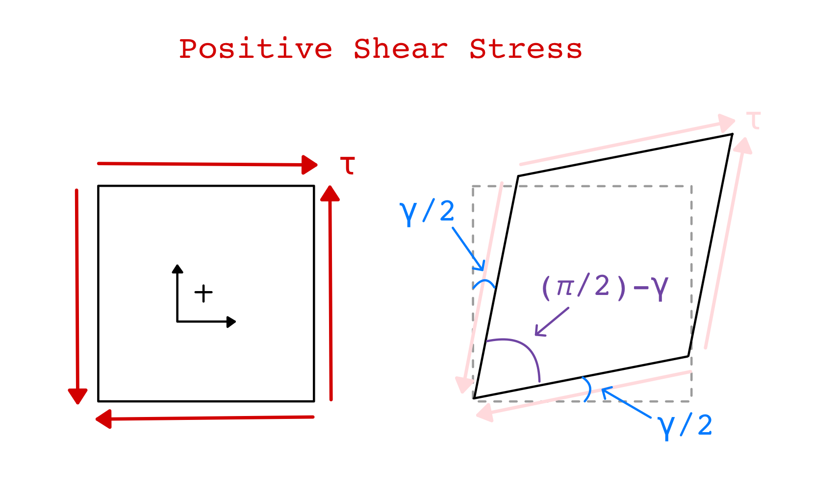
Shear Strain is the measure of distortion or change in shape. Measured in degrees or radians and denoted by
Hooke’s Law in Shear:
Shear Modulus of Elasticity (Modulus of Rigidity):
Factor of Safety
Strength: the ability of a structure to resist loads
Factor of safety: the ratio of actual strength to required strength; must be above 1.0 to avoid failure
Margin of Safety: extra capacity a material has beyond failure. This is expressed as a percentage
Allowable Stress
Allowable Stress: maximum stress that a structure can safely withstand under working conditions without failure or permanent deformation.
If the ultimate stress is used instead of the yield stress, the equations are the same, but with the perspective of factor of safety.
Allowable Loads
Allowable load: The maximum force a structure can withstand before failure or permanent deformation
Design Factors
Stiffness: ability of a structure to resist change in shape
Stability: ability of a structure to resist buckling under compressive stresses
Example 1:
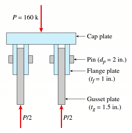
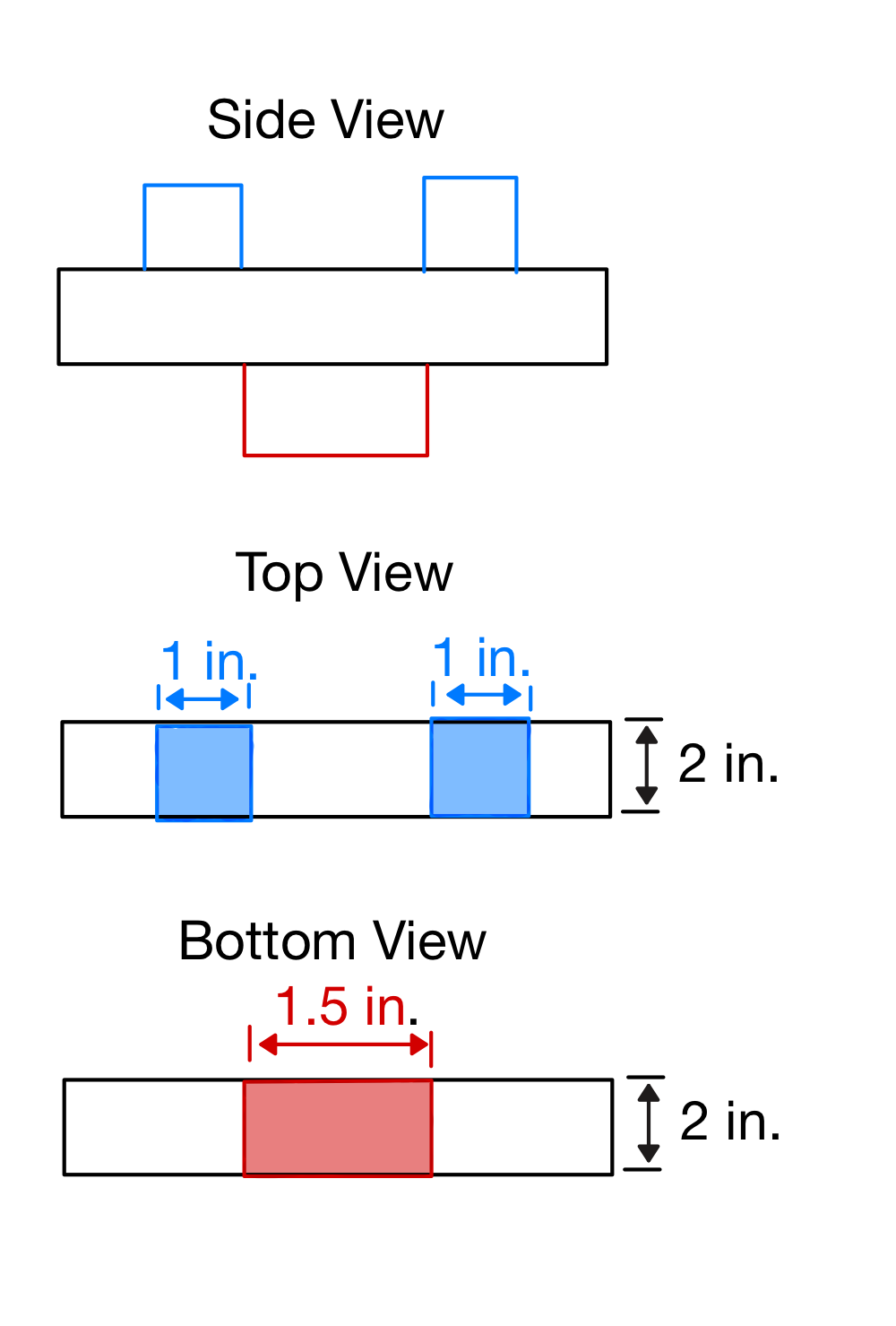
Problem 1.8-3: Given the diagram below, find , between the flange and plates, and between the gusset and the pin.
Average Shear Stress:
-
Find area that is resisting shear:
-
Solve Shear Stress:
since the pin is in double shear, and V=P/2
Bearing Stress between the flange plates and the pin:
-
Find the force of the flange plate:
There are two flange plates for each gusset plate, so
-
Find the bearing area:
-
Find Bearing Stress
Bearing Stress between the gusset plate and the pin:
-
Find the force of the gusset plate:
The gusset plate provides a force of
-
Find the bearing area:
-
Find bearing Stress:
Example 2:
Problem 1.10-1
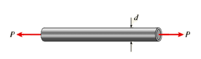
What is the outside diameter when P=33 k, the thickness of the tube is 0.25 in, and the allowable tensile stress is 12,000 psi?
-
Use the allowable stress equation to find the needed cross-sectional area
-
Use the area of a circle to find the outer diameter
3.75 in