Mohr’s Circle
Introduction
Mohr’s Circle is a graphical method used to determine the principal stresses, shear stress, and the orientation of stress elements. It transforms a known state of plane stress into any rotated orientation without repeatedly using the stress-transformation equations.
Constructing Mohr’s Circle
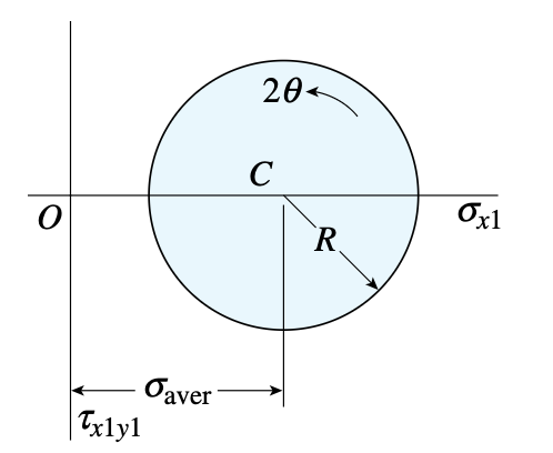
Stress () is on the x-axis (positive to the right) and shear stress () on the y-axis (positive down).
Center:
Radius:
The principal stresses and occur where the circle crosses the horizontal axis:
Given in the problem, the two stress points are and for the x-plane and y-plane, respectively. These two points, plotted on Mohr’s Circle, form the diameter of the circle and serve as the reference point to help us find the principal angles, and .
The radius of the main Mohr’s Circle is the maximum in-plane shear stress (). Two other circles can be drawn by connecting and as well as and . The radius of the largest circle gives the (.*?) ().
Principal Angles
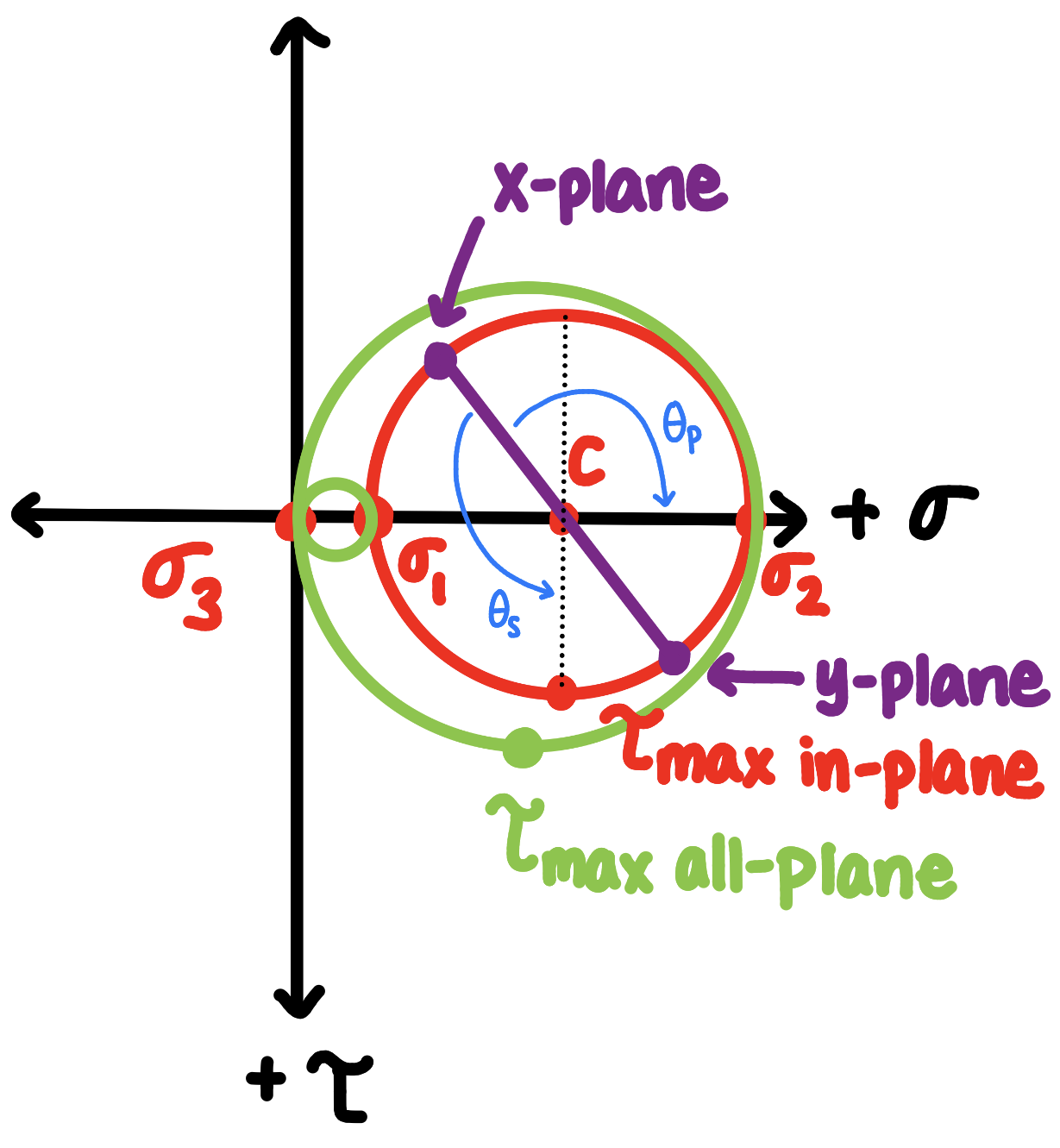
The principal-angle equations can be misleading because the inverse tangent only returns an angle in the correct reference angle, not necessarily the correct quadrant.
In other words, these equations calculate the angle to the nearest principal or shear axis, respectively. But we want to find the angle to the positive principal or shear axis. Therefore, we must verify what quadrant we are in and, if necessary, add or subtract 90° to obtain the angle to the positive principal or shear axis. See the figure to the right as an example of this.
Other Things to Remember About Mohr’s Circle
-
A physical rotation of of an element corresponds to a rotation of on Mohr’s Circle.
-
Clockwise is negative, and counterclockwise is positive.
-
Maximum shear is 45° from the principal planes (90° on Mohr’s Circle).
-
Principal stresses occur where shear stress is zero.
Example: Find the principal stresses, maximum in-plane shear stress, the principal and maximum shear angles, and draw the corresponding stress elements given the element is subjected to the following stresses:.
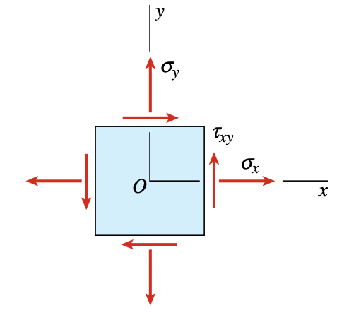
Center & Radius:
Principal Stresses:
Drawing Mohr’s Circle & Finding Angles:
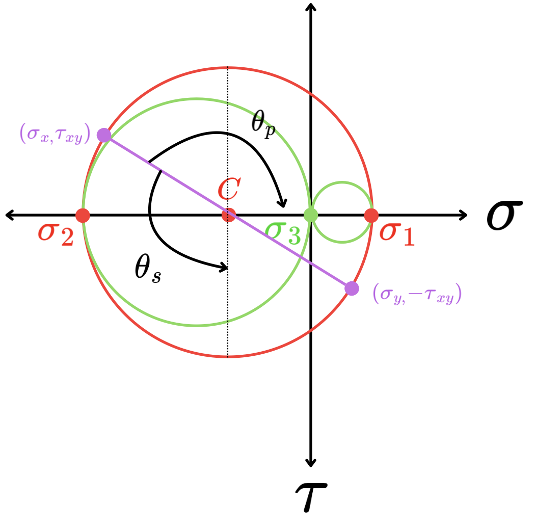
However, this angle is measured to the negative stress axis, since that is the closest x-axis. Therefore, we need to subtract 90 degrees: . It makes sense to get a negative result, since is clockwise (see figure).
However, this is also measured to the negative shear stress axis, since that is the closest y-axis. Therefore, we need to add 90 degrees: . It makes sense to get a positive result, since is counterclockwise (see figure).
Therefore, and .
Stress Element & Shear Element Drawings
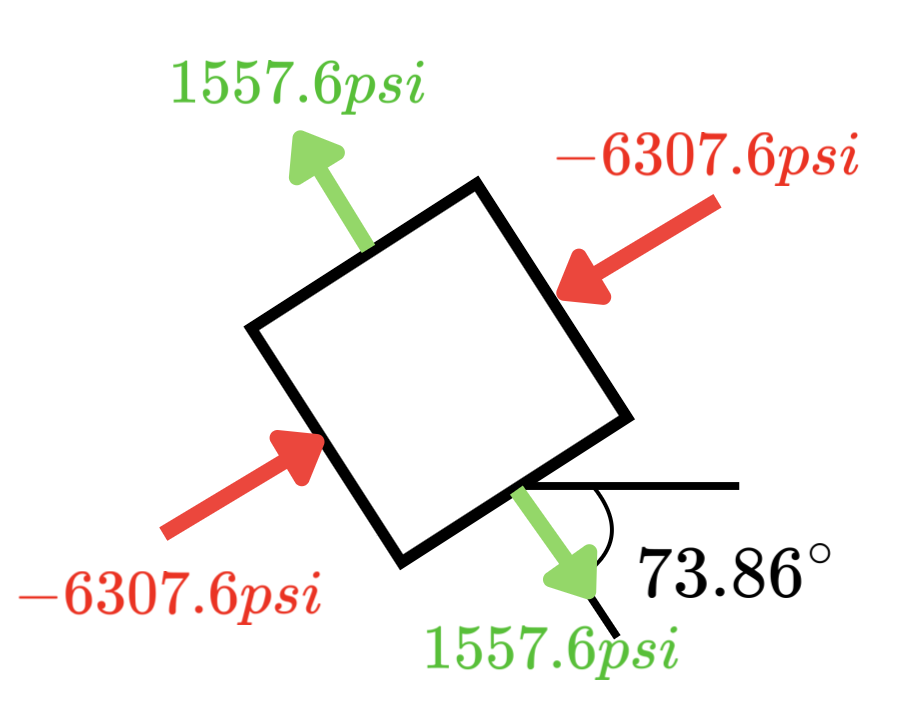
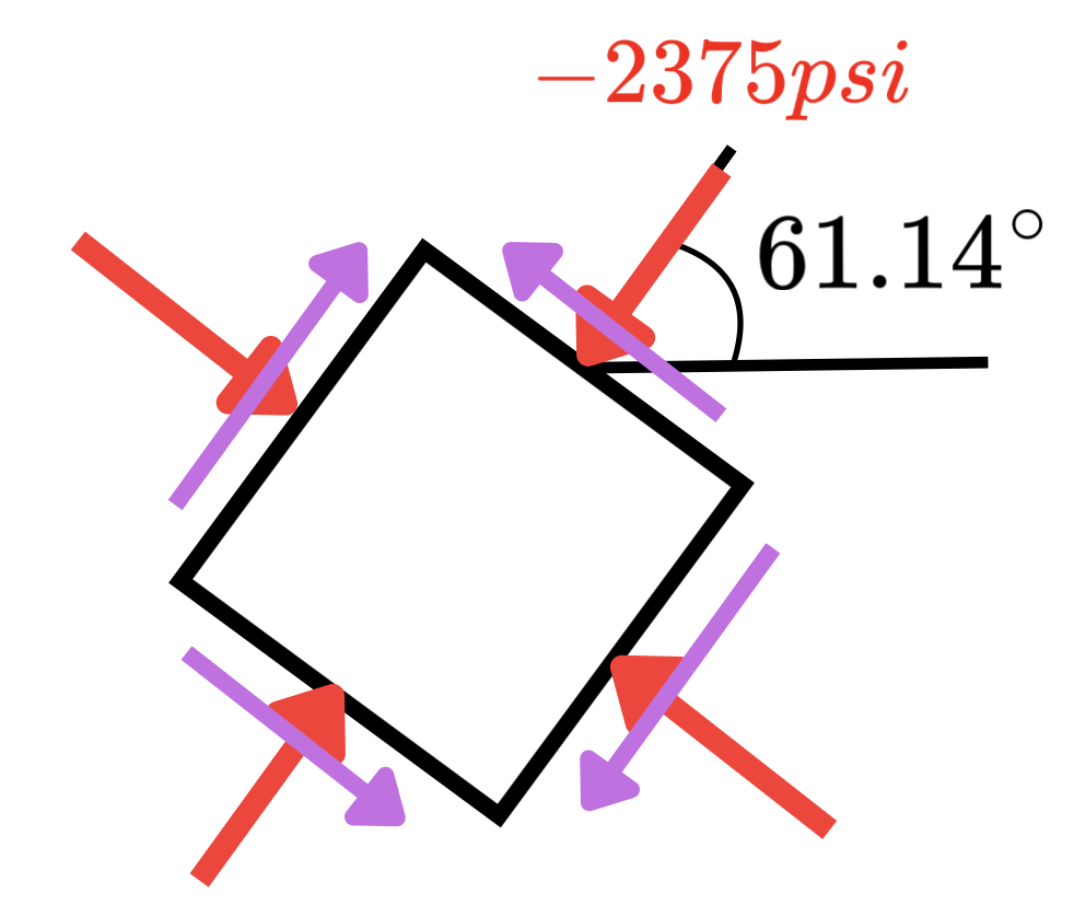
Now that we have these angles, we can draw the stress element (left below) where the shear stress is zero and the shear element (right below) where the shear stress is at a maximum.