
Series DC Circuits
Introduction
A series DC circuit contains electrical elements connected along a single current path. The current is the same through every element in a series path, while the source voltage is distributed among the elements according to their resistances.
Current in Series
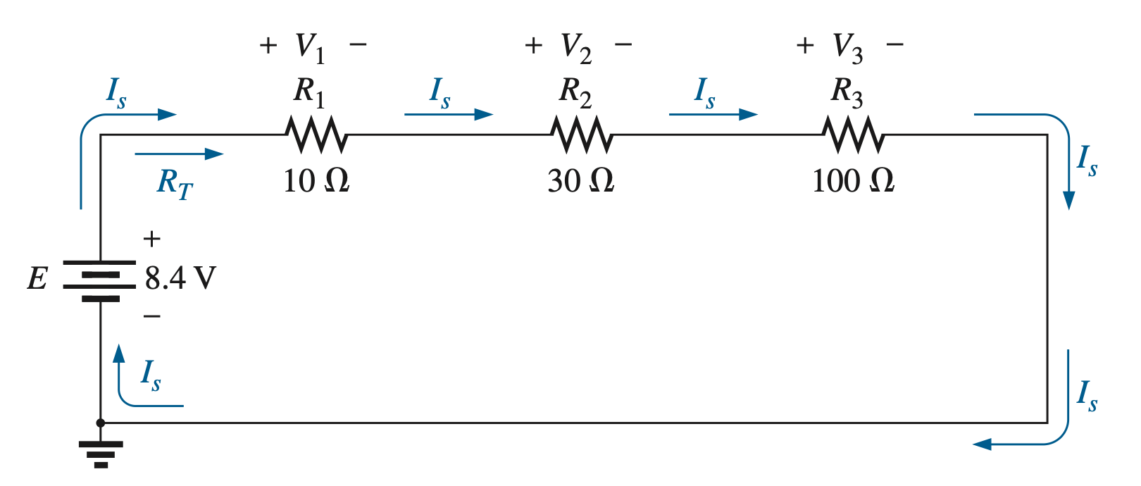
Elements are connected in series when they share the same current, and there is no branching between them:
Resistance in Series
The total resistance of resistors connected in series is the sum of the individual resistances:
Circuit Current & Voltage Across Series Resistors
Once the total resistance is known, use Ohm’s Law to calculate the circuit current:
If every resistor is in series, this is the current through every resistor in the circuit. Therefore, the voltage across an individual resistance is:
. . .
Kirchoff’s Voltage Law (KVL)
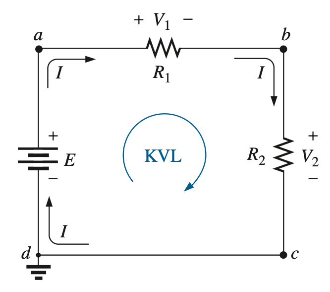
Kirchoff’s Voltage Law states that the sum of all voltage changes around a closed loop is zero. In other words:
For a single-source series circuit:
Voltage Divider Rule
In a series circuit, the source voltage divides between resistors based on their resistances. For two resistors in series:
In other words, the voltage through a resistor is the total voltage times its voltage fraction .
Example 1: Find the total resistance, current, voltage through each resistor, and power delivered by each resistor.
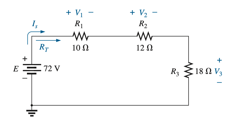
1) Since all three resistors are in series, the total resistance is the sum of their individual resistances:
2) Using the total resistance and the source voltage, we can find the current:
3) The voltage and power for each resistor is found with the current and individual resistances:
Note that the sum of the individual voltages equals the source voltage of 72 V, which is consistent with Kirchoff’s Voltage Law.
Example 2: Find the sissing resistance using the voltage divider rule.
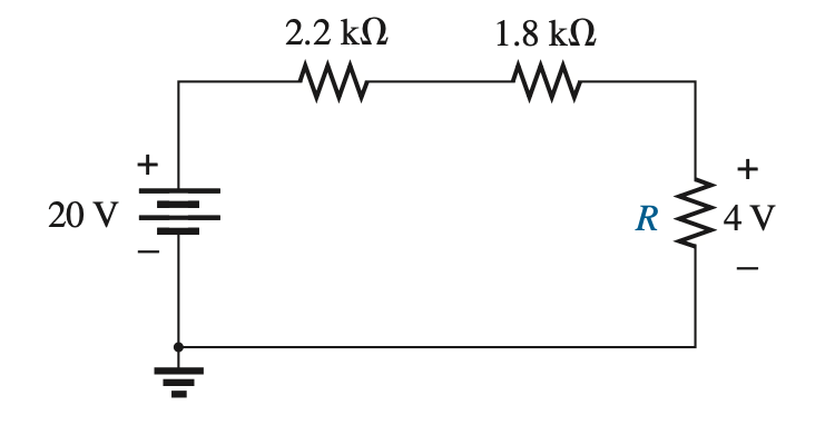
Plugging in to the voltage divider rule:
Solving by graphing: