Series-Parallel Combinations of Capacitors and Inductors
Introduction: This article focuses on combining multiple inductors and capacitors within a circuit to simplify analysis.
The Essentials
Just like resistors can be combined in to a single resistor, capacitors and inductors can be simplified into a singular capacitor and inductor.
For inductors in series, each inductance carries the same current and is described as the same equation, \( v = L\frac{di}{dt} \). So to simplify, we get the following for series-connected inductors.
For inductors in parallel, this equation describes combining those.
Capacitors in series can also be expressed as a single capacitor. They are expressed as the following:
For capacitors in parallel, they can be described as the following:
Example
Let's do an example of combining capacitors and inductors into a singular capacitor and inductor. Figure 1. has an example of a circuit which we would like to analyze

Figure 1: Series Example Schematic
We notice a couple of things with this circuit; all elements of the circuit are in series so we can combine each respective element according to their equations.
\[ L_{eq} = L_1 + L_2 = (178 \, \text{mH} + 265 \text{mH}) = 443 \, \text{mH}\]
\[ \frac{1}{C_{eq}} = \frac{1}{C_1} + \frac{1}{C_2} = \frac{1}{470\cdot10^{-3}} + \frac{1}{860\cdot10^{-3}} \, \rightarrow C_{eq} = 304 \, \text{mF}\]
Let's do an example of parallel inductors and capacitors, shown in Figure 2.

Figure 2: Parallel Example Schematic
Similar to the previous, we recognize that the elements are in parallel with one another. We use the equations related to each respective element.
\[ \frac{1}{L_{eq}} = \frac{1}{L_1} + \frac{1}{L_2} = \frac{1}{780\cdot10^{-3}} + \frac{1}{810\cdot10^{-3}} \, \rightarrow L_{eq} = 2.52 \, \text{H}\]
\[ C_{eq} = C_1 + C_2 = (560 \, \mu\text{F} + 630 \mu\text{F}) = 1.19 \, \text{mF}\]
Practice
- Using Figure 3., solve for \( C_{eq} \).
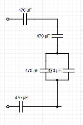
Figure 3: Problem 1 Schematic
- Using Figure 4., solve for \( L_{eq} \).

Figure 4: Problem 2 Schematic
- Using Figure 5., solve for \( C_{eq} \).

Figure 5: Problem 3 Schematic
- Using Figure 6., solve for \( L_{eq} \).

Figure 6: Problem 4 Schematic
Solutions:
Problem 1 Solution.) \( C_{eq} = 134 \, \mu\text{F} \). For this circuit, we recognize that there are only two capacitors in parallel and rest are in series. Let's solve for \( C_{eq} \).
\[ \frac{1}{C_{eq}} = \frac{1}{470\cdot10^{-6}} + \frac{1}{470\cdot10^{-6}} + \frac{1}{940\cdot10^{-6}} + \frac{1}{470\cdot10^{-6}} \rightarrow C_{eq} = 134.28 \, \mu \text{F}\]
Problem 2 Solution.) \( L_{eq} = 667 \, \text{mH} \). Seeing the circuit diagram, we can easily recognize parallel and series connections. Below is the equation to realize \( L_{eq} \). Remember that \( \parallel \) is the parallel symbol so use equation 2 accordingly.
\[ L_{eq} = (((370 \parallel630)+800) \parallel700) +250 = 667 \, \text{mH}\]
Problem 3 Solution.) \( C_{eq} = 79.84 \, \mu \text{F} \). This equation follows the connections between each capacitor. Note: the '--' symbol represents series connections
\[ C_{eq} = ((290-- \, 450) \parallel 890) --\, 630 -- \, 100 \rightarrow C_{eq} = 79.84 \, \mu\text{F}\]
Problem 4 Solution.) \( L_{eq} = 599 \, \text{mH} \). Analyzing the circuit, we get the following equation representing the connections.
\[ L_{eq} = ((980 \parallel 360) + 580 + 750) \parallel (270 + 690) = 599 \, \text{mH}\]