LIDAR Assisted Rendezvous and Docking
Summary
Autonomous close in maneuvering rendezvous and docking of spacecraft, without active 'man-in-the-loop' control, has been extensively studied. The critical tool required for these maneuvers has been a relative navigation sensor, which can determine the relative position and orientation of the controlled spacecraft with respect to the target spacecraft. Current methods use 2D visual cameras and extensive image processing to determine the position and range of a cooperative target. Lidar systems have been proposed as a complement or replacement for these imaging systems. Unlike visible cameras, their performance is completely independent of ambient lighting conditions. Lidar systems provide accurate range information to specific points on a target with accuracies in the 1 to 3 cm range with 0.05? angular resolutions. Three-dimensional "point-cloud" images can be generated by either scanning the laser beam in two dimensions or using a pixilated "flash" LiDAR camera. These 3D images contain significantly more navigational information than a traditional 2D imager. Currently, testing has been done using lidar-based navigation methods to locate the position and orientation of a nearby spacecraft in simulation. Position and attitude can be determined by comparing the point cloud data measured by the lidar with point-clouds generated by a solid model of the spacecraft using the point cloud matching algorithm known as the Iterative Closest Point (ICP) method.
Iterative Closest Point (ICP) Algorithm
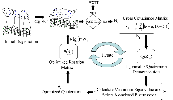
The Iterative Closest Point (ICP) algorithm has become one of the dominant registration methods in the literature for aligning a pair of range images, or globally aligning several pairs of 3-D point based range images. Originally developed by Chen and Medoni and Besl and Mckay, the ICP algorithm takes two sequentially acquired range images and calculates the registration parameters: the quaternion describing the rotation matrix between the target and the lidar and the cartesian translation vector between this pair of range images. Since the ICP algorithms introduction, many different variants have been developed, which improve upon the basic concepts and steps in the algorithm, and were studied by Rusinkiewicz and Levoy. These sequential steps are as follows: (1) initialization, (2) selection of points, (3) calculating point-to-point or point-to-plane correspondences, (4) calculating registration parameters, and (5) minimizing an error metric.
| Three Axis Roation | No Noise (°) |
2cm (°) |
Noisy (°) |
|---|---|---|---|
| Maximum Mean Angular Error | 0.055 | 0.490 | 0.800 |
| Minimum Mean Angular Error | 0.052 | 0.065 | 0.349 |
| Average Mean Angular Error | 0.053 | 0.181 | 0.462 |
| 1 σ – Standard Deviatiation | 0.030 | 0.196 | 0.325 |
| Single Axis Rotation | No Noise (°) |
2cm (°) |
14cm (°) |
|---|---|---|---|
| Maximum Mean Angular Error | 0.079 | 0.129 | 0.494 |
| Minimun Mean Angular Error | 0.031 | 0.024 | 0.383 |
| Average Mean Angular Error | 0.423 | 0.070 | 0.423 |
| Average 1σ– Standard Deviatiation | 0.267 | 0.044 | 0.267 |
Point-Cloud Models
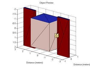
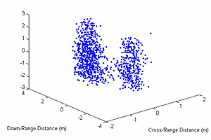
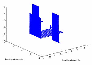
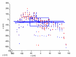
This project employed the direct use of a 6 DOF pose estimation algorithm (i.e. ICP algorithm), which uses sequentially gathered range images, also known as "point clouds", to calculate 6 DOF relative/absolute position data. The first method used to obtain point cloud models was through a simulation software package, LiDARSIM, which incorporates performance-related parameters associated with the laser, detector, signal processing, scanner dynamics, platform dynamics, navigation errors, and scene properties to provide general system analysis, error source modeling, and 3-D points clouds. A simple solid model of a spacecraft was used in this program to create a point-cloud image. The simulated point cloud was generated assuming the range between the lidar and the target was approximately 1 km. The angular resolution between shots was 100 µrad with an RMS range error of 0, 2, and 14 cm, based on realistic lidar transceiver error models. Experimental point cloud models are currently obtained from a Canesta Model# DP205 55 degree field-of-view flash lidar imager; however, the data gathered was inadequate for determining 6 DOF pose with current MATLAB ICP code.
Conclusions and Future Works
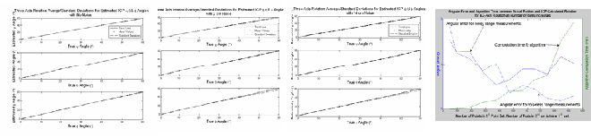
Results obtained show that as long as the point sets overlap, then the MSE, rotational errors, and standard deviations for position and orientation registration between the ranges of 1º-60º did not vary, but showed increases in computational time as the number of points increased. The first of several tasks that are being considered for future research, will be to construct an algorithm that exploits the geometry of the 3-D point cloud, such that, a reasonable guess for a initial alignment can be obtained (i.e. MACH Filtering, Neural Networks, etc). Finally, an extended Kalman filter will be implemented in the MATLAB GUI environment for real-time capabilities with the Rusinkiewicz ICP variant.
[1] R. Fenton,, R. R. Fullmer, and R. Pack, Design of lidar-based sensors and algorithms for determining the relative motion of an impaired spacecraft, SPIE Paper 5778-114, SPIE Defense and Security Symposium, Orlando, FL, March 28 - April 1, 2005.