Wheel Hub Sensor
Team: Ethan Lane, Casen Miller and Caleb Olsen
Project Background
Create a device that identifies and warns drivers when signs of wheel failure appear. The device needs to measure the vibrations, temperatures, and tire pressure of each wheel. When a problem is identified, such as excess vibrations, high temperatures, or dropping tire pressure, the system will notify the driver through the driver’s smartphone.
Design Description
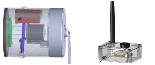
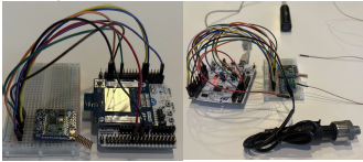
The design consists of two primary devices.
The Wheel Devices – Mounts onto the wheel hub. The tire pressure, vibrations, and temperatures are measured by a pressure transducer, accelerometer, and thermocouple. These values are then sent via radio.
The Chassis Device – Receives the transmissions from the wheel devices, records the vehicle’s location via GPS, and sends those values on to the driver with Bluetooth.
Performance Overview
The predicted performance was obtained using the datasheets and info available from the manufacturer. The actual performance was obtained from testing the individual components for completed parts and analysis based on the current design for parts that are still in progress.
| Requirements and Constraints | Target | Threshold | Predicted Performance | Actual Performance |
|---|---|---|---|---|
| Vibration Measurements | 0-300 Hz | 0-300 Hz | 0-300 Hz | 0-300 Hz |
| Bearing Temperature Measurements | N/A | 0 - 220 °F | -100 – 500 °F | -100 – 500 °F |
| Brake Temperature Measurements | N/A | 0 - 1200 °F | -328 - 2300 °F | -328 - 2300 °F |
| Tire Gauge Pressure Measurements | 0 psi to 150 psi | 75 psi to 150 psi | 0 psi to 150 psi | 0 psi to 150 psi |
| Transmission Time Interval | 5 seconds | 60 seconds | 0.74 seconds | 0.55 seconds |
| Transmission Distance | 300 ft | 120 ft | 400 ft | 460 ft |
| Operable Temperature Range | N/A | -40°C to 80°C | -40°C to 80°C | -40°C to 80°C |
| Weatherproofing | N/A | IP67 | IP67 | IP67 |
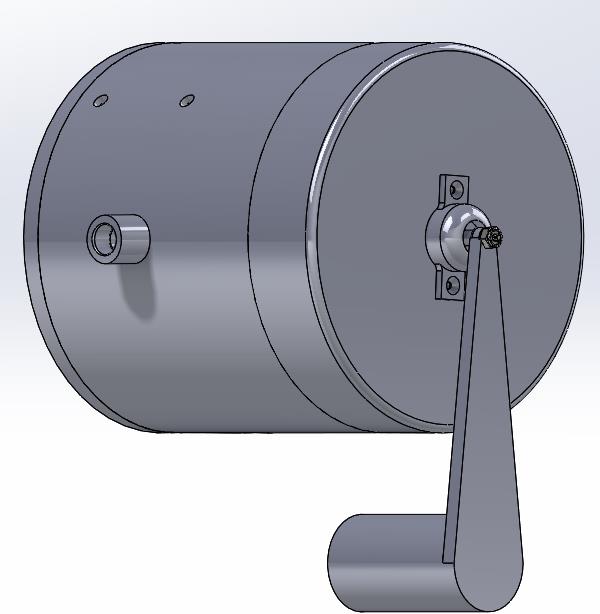
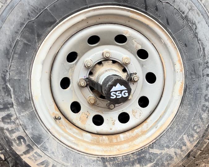
Mounting
The wheel device is mounted onto the wheel hub as shown below. The device has a weight hanging below that stays stationary when the wheel rotates. This weight is what drives the motor to generate power.
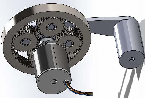
Power Generation
There is a planetary gearbox inside the module. This gearbox transfers the rotation of the wheel to aDC Motor, generating power. The gearbox works in a 4:1 ratio, allowing for power generation at low RPM.
Communication
The wheel and chassis devices both contain microcontrollers on their PCBs. The wheel microcontrollers take various measurements and then communicate via radio frequency with the chassis device. The chassis device sends the values to the phone via Bluetooth.
Future Work
The next steps for this project are to continue with the debugging of the software, design a printed circuit board, and begin production of the wheel device and printed circuit board. This will lead to the first real-sized prototype, with more iterations to follow.
Conclusion
Design Requirements: The design is currently either meeting or projected to meet all design requirements. The requirements need to be regularly reviewed in future iterations.
Lessons Learned: The team learned the importance of talking with experts in various areas, of client communication, and of small consistent goals during the design.
Special Thanks to Karsten Jacobson Jr. and Karsten Jacobsen Sr. from Trailering U for their support of this project