Shredder Hammer Lifter
Team: Halen Martini, Gabe Stagg and Matt Withers
Performance Review
| Requirement / Constraint | Target | Threshold | Predicted Performance | Actual Performance |
|---|---|---|---|---|
| Device weight | 350 lbs | Under 4 Tons | 292 lbs | 329 lbs |
| Maximum width of object the device can lift | N/A | 4.75″ | 4.875″ | 4.920″ |
| Device lift capacity | N/A | 500 lbs | 500 lbs | 500+ lbs |
| Device lifetime | 20 years | 8 years | 20+ years | Infinite |
| # of devices needed | N/A | 1 | 1 | 1 |
| Eyelet diameter for crane hook connection | N/A | 2.5″ | 2.5″ | 2.5″ |
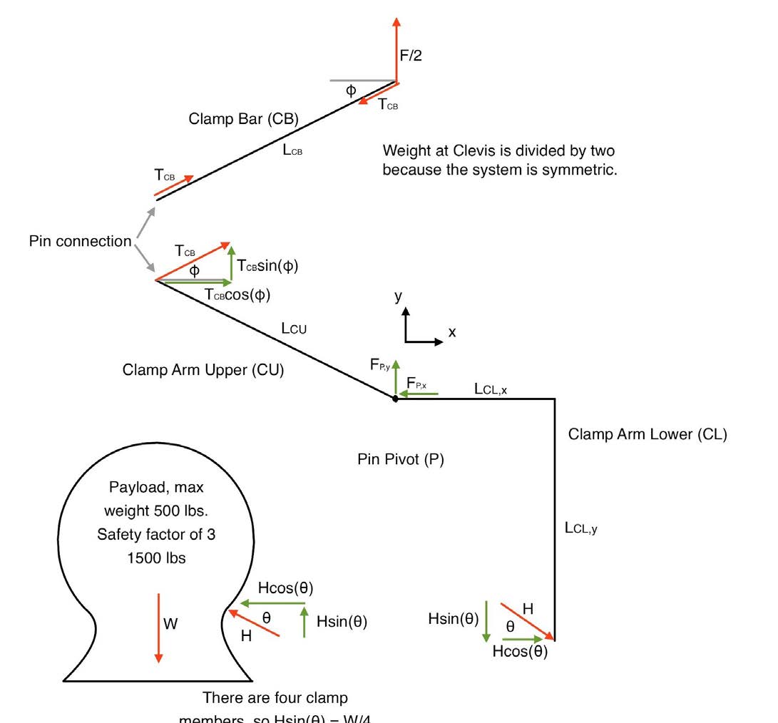
Static Force Analysis – Lift
A static analysis was performed on one side of the clamp.
FEA Simulation – Lift and Lifetime
FEA Simulations were performed on the clamp arms (left) and bars (right) to analyze loads from clamping force and the hydraulic cylinder. Stress and Fatigue were analyzed.


CAD Model Review – Number of Devices, Weight, and Width
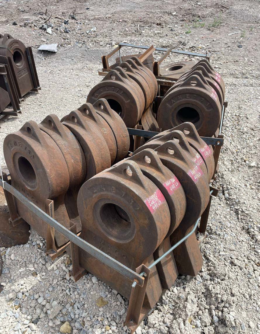
Hammers


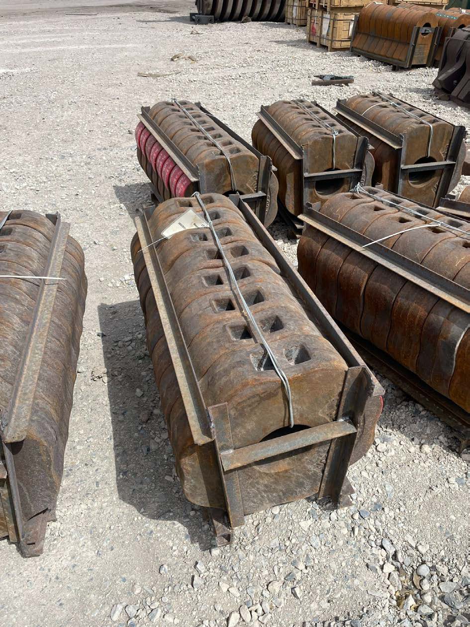
Pin Protectors


The team placed the CAD of new (left) and worn (right) hammers and pin protectors inside the clamp to ensure a secure fit for both.
The projected weight of the clamp was collected from SolidWorks.
The side-view of the clamp was analyzed to verify the maximum width of hammer or pin protector.
Project Description
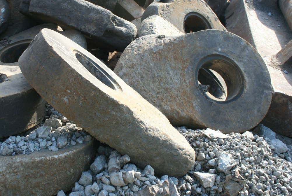
Western Metals Recycling (WMR) uses large hammers and pin protectors to shred metals. While shredding, the 500 lb hammers and pin protectors sustain significant damage and wear, requiring a 1–6 hour replacement on a weekly basis.
We created a device that speeds up the replacement process and does not require welding. The device lifts worn and new hammers and pin protectors out of a rotor system during installation or removal.
Design Description
- Clamp Bars
- Clamp Arms
- Chamfered Containment Panels
- Load-Bearing Tapered Spacers
- Battery
- Electrical Components
- Receiver
- Hydraulic Cylinder
- Shackle
- Wireless Remote
![CAD Assembly with Callouts 1–10. (starting at the top [noon] and going clockwise) 9, 1, 2, 3, 4, 5, 6, 7, 8. 10 is seperate and off to the left-hand side](/images/senior-design/fall2025-spring2026/mae/shredder-hammer-lifter/design-description.png)
Conclusion
Analysis Results
- Static analysis shows a clamping safety factor of 3.43 (≥1500 lb capacity)
- FEA gives a minimum tensile safety factor of 4.27
- Fatigue life predicted at 1,000,000 cycles
- Final weight: 329 lb (vs. 292 lb predicted)
- Clamp width: 4.920 in (vs. 4.875 in. CAD)
- One clamp can lift both hammers and pin protectors
- Hardware and shackle verified to meet load requirements
Lessons Learned
- Complex systems require multiple engineering disciplines
- Electrical integration required outside expertise (WMR support)
- Proactive scheduling is critical — manufacturing delays impacted timeline
Recommended Future Work
- Develop a multi-clamp system mounted on a rod
- Match clamp spacing to rotor layout
- Enable simultaneous installation/removal
- Move toward fully autonomous operation
Special thank you to Josh Fonger, Tyrel Skinner, and Preston Stith for their support in completing this project!