Multi-Surface Mesh Radio
Team: Braxton Buttars, Parker Mayer, Trevan Nelson, Cade Park, Ben Simpson and Luke Summer
Project Description
Soldiers communicate wirelessly via radio networks that rely on radio towers or line-of-sight between radios. However, radio towers are not available in every military situation. This project aims to develop a lightweight, lowcost radio relay that can attach to a nearby surface and act as a radio repeater when radio towers are not present.

Mesh Radio Network
The radio repeaters must wirelessly connect to other repeaters form a mesh radio network. A mesh radio network consists of multiple nodes that send radio signals to each other. This allows soldiers to communicate around obstacles that block the receiver from the transmitter.
Design Description
Mechanical Design
The radio relay contains all the electrical components and physical attachment methods to produce a working radio repeater. On the back of the relay, magnets allow it to attach to magnetic surfaces. The relay has a belt clip that can attach to thin surfaces or to the claw clip to provide additional attachment methods.
On the claw clip, the spring-loaded claw provides attachment by clamping around any object it can surround. On the back of the claw clip is a spring-loaded cam that can wedge between cracks.
The radio relay is carefully designed to make the relay waterproof. Gasket material is placed anywhere the electrical components can be exposed to the external environment. A screw-on aux port cap prevents water from leaking in through the aux port.

Radio Relay

Claw Clip
Electrical Design
The electronic brains behind the relay is an ESP32-S3. An amplifier located after the aux port amplifies the voice going into the ESP32-S3. Multiple filters reduce unwanted noise in the sound that is transmitted across the mesh network. The ESP32-S3 also accepts inputs from the two buttons to control the lights and electrical functions accordingly.
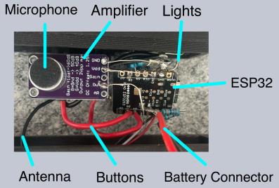
Electrical Circuit
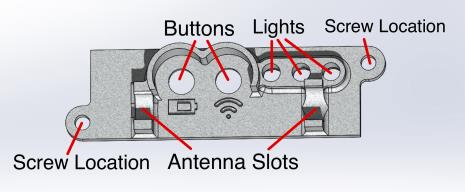
User Interface
As shown in the image below, the relay’s user interface contains 2 buttons and 3 lights. The left button can be held to turn on/off the relay. It can be pressed to test battery power (green means good, yellow means low, and red means extremely low).
The right button can be held to wirelessly connect and transmit a message from one relay to other relays. It can be pressed to test connection strength (green means good, yellow means weak, and red means no connection).
To use the relay, the user turns it on and connects it to other relays within line-of-sight. The user then plugs their headset into the aux port and pushes the right button to speak. The message is then sent across the mesh radio network to another user who hears the message through their own headset plugged into a relay.
The battery compartment contains a flip-top lid. The user can open this compartment without the need for any tools. The battery can then be manually disconnected and replaced.
Relay Lid
Performance Review
| Requirement | Target | Threshold | Actual |
|---|---|---|---|
| Cost | $20 | $50 | $32.86 |
| Weight | 0.5 lbs | 1 lb | 0.45 lbs |
| Working Number of Relays | 10 | 4 | 5 |
| Range | 1 mile | 0.25 miles | 0.4 miles |
| Transmission Type | Voice | Data | Voice |
We tested each requirement to verify whether it met the target and threshold. Our final product meets the target for all requirements except range, where it meets the threshold but not the target. Because the mesh radio is used to facilitate communication, we chose to focus more on the transmission type rather than the range.

Radio Relay Weight Verification
Conclusions
Our final product meets all of the requirements given in the project. Ultimately, we learned to prioritize the most important requirements first that would yield a useful product. Prioritizing requirements helps future contributors to easily improve upon the current design.
We also learned to build and test our product early. Early electrical testing revealed that our aux port was insufficient for voice transmission. Because we tested early, we were able to obtain the correct equipment and stay on schedule.
For future work, we recommend more research into clearing up the voice transmission. The current voice transmission, which contains some static, could be improved. Additionally, increasing the range with a new antenna and ensuring the mesh code is functioning properly could make it more practical in military scenarios.