Fabric Low-Cost Expendable Airframe
Team: Erik Bodily, Daniel Olsen, Logan Soderborg and Ethan Syphus
Project Description
Agriculture, environmental monitoring, and disaster response increasingly depend on affordable unmanned aerial systems (uas) that can be deployed quickly and in large numbers. current commercial drones are limited by high cost, long lead times, and difficulty scaling operations across wide areas. this project is to develop a novel fabric, low cost, expendable airframe (flex) that can be manufactured in under one hour, using low-cost materials, and packed densely into standard containers for easy transport. this approach offers farmers, researchers, and emergency responders an accessible tool for large-area monitoring and data collection without the prohibitive expenses of traditional airframes.
Performance Review
| Requirement/Constraint | Target | Threshold | Actual Performance |
|---|---|---|---|
| Wingspan | 3m | 5m | 3m |
| Cost (Per Unit) | $2,000 | $3,000 | $2,421 |
| Takeoff Weight | N/A | 10 kg | 10 kg |
| Cruise Velocity | 20 m/s | N/A | 20 m/s |
| Field Assembly Time | 30 min | 60 min | 40 min |
| Disassembled Size | 20 mm Ammo Can | 33" Pelican Case | 20 mm Ammo Can |
| Payload Capacity | 2 kg | 1 kg | 2 kg |
Wind tunel testing: initial characterization of the flex system was carried out through wind tun el testing to verify analytical approach.
Six degree of freedom flight simulation: flight simulation was conducted to verify airframe design prior to manufacture.
Flight testing: following manufacture of the airframe, flight testing was performed to verify design requirements and drive design iteration.
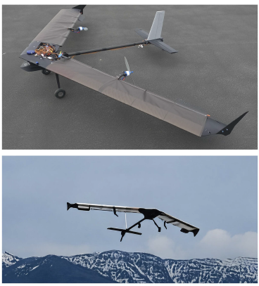
Design Description
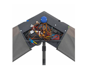
Our uav design is composed of 4 major components; mechanical zone, wings, tail, and slim p.
The mechanical zone is centered on the aircraft and is the location where each component can interface. the mechanical zone also contains the avionics and other electronic devices.
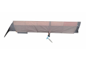
The wings are constructed with a carbon fiber skeleton covered by a dyneema wing skin. springs at the trailing edge of the wing create tension in the fabric.
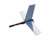
The tail section is a T style configuration and holds the major control surfaces. additionally the rear landing gear is positioned there.
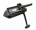
the blimp underneath the aircraft is used to carry the battery and payload.
Conclusion
Our design meets all major requirements presented by the customer. future improvements should include the implementation of a tilt rotor configurtion. additionally efforts need to be taken to improve ease of manufacture as production scales.
We learned the importance of clear comunication during the design of subsystems and the importance of rapid prototyping.
We would like to thank Cal Coopmans and Zeb Astle for their contributions to this project.