Design Build Fly
Team: Drew Barnard, Luke Berrigan, Carson Child, Daniel Estes, Mason Frederick, Benji Hansen, Max Jeppson, Jerith Larsen, Jackson Mandry, Ethan McGregor, Matt Orr, Warren Prescott, Andrew Riggs, Clint Tolbert and Brock Whitaker
Problem Description
We were tasked with designing an airplane for AIAA's Design, Build, Fly competition. This year, the competition asked for a bush airplane style design. There are 4 missions in the competition.
- Mission 1 – Test Flight: Prove the plane can fly.
- Mission 2 – Payload: Carry as many rubber duck passengers and cargo hockey pucks as possible in as many laps of the course as possible.
- Mission 3 – Banner Tow: Tow a vertical banner behind the aircraft for as many laps of the course as possible.
- Mission 4 – Ground Mission: Load and unload the aircraft in the shortest time possible.
Design Description
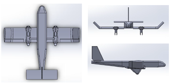
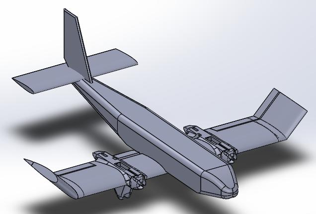
Airframe: The airframe is a single fuselage, twin engine aircraft. It is made of PETG 3D printed parts and lightweight foamboard. The dimensions of the airframe are given in Table 1. See Figure 1 and 2 for the general shape of the airframe.
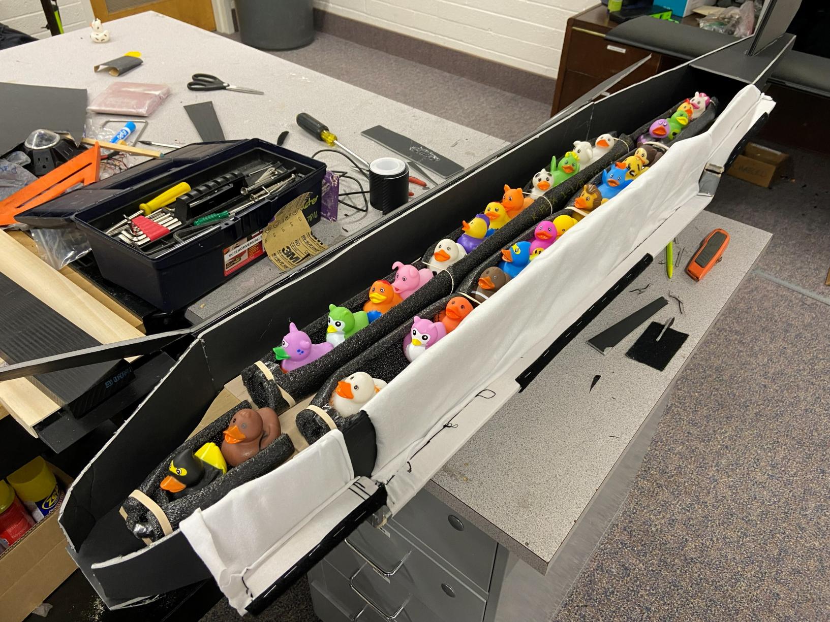
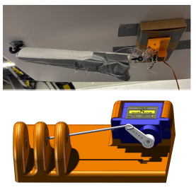
Passenger Restraints: The passenger restraint system is made of pool noodles cut to allow rubber duck passengers to sit in the upright position. They are held in place by a cloth covering that is wrapped over the top and rigidly attached to the other side with Velcro. This prevents the ducks from coming loose in flight. See Figure 3.
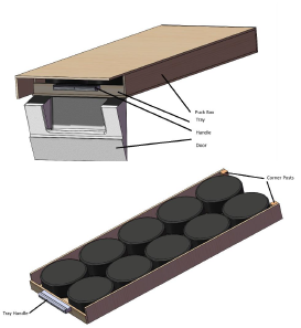
Cargo Compartment: The cargo compartment is a balsa wood box that has a drawer in it. The front door is chisel shaped to reduce drag on the box. The drawer has a handle that allows for quick removal for loading and unloading. The pucks are laid down flat inside the drawer for flight operations.
Banner Release: The banner is a 1x5 ft canvas piece that is held stowed by a bar going through it. The release mechanism holds this rod securely to the plane for takeoff. When released, the servo moves a rod to the position that releases the stowage rod but hold the banner behind the plane. When the banner needs to be released, the release mechanism is moved to the next position that allows the banner to completely detach from the airplane. See figure 5.
Table 1: General Dimensions
| Dimension | Value |
|---|---|
| Length | 5.17 ft |
| Wingspan | 5 ft |
| Height | 2.17 ft |
| Weight | 18 lbs |
Table 2: Requirement Thresholds and Actual Performance
| Requirements/Goals | Target | Threshold | Actual |
|---|---|---|---|
| Aircraft Weight | 20 lbs | 55 lbs (max) | 18 lbs |
| Wingspan | 5 ft | 5 ft (max) | 5 ft |
| Banner Length | 5 ft | 10 in (min) | 5 ft |
| Banner Height | 1 ft | 2 in (min) | 1 ft |
| Ducks Carried | 30 | 3 (min) | 30 |
| Pucks Carried | 10 | 1 (min) | 10 |
| Battery Capacity | 80 Wh | 100 Wh (max) | 118 Wh |
| Laps | 6 | 1 (min) | Unknown |
| Speed | 70 mph | 62 mph (min) | Unknown |
Performance
Mission 1 – Test Flight
Initial test flights proved the designs strengths. However, several major design changes needed to be made to improve the stability of the plane in flight. The major changes that needed to happen were:
- Increased control surface (aileron, elevator, rudder) area to improve controllability of the plane.
- Improve the roll stability of the plane.
- Shift the center of gravity forward.
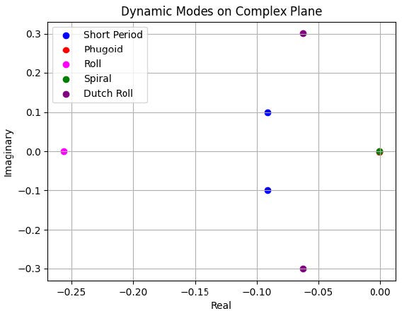
The graph below shows the results of the dynamic stability analysis of the improved plane. All points should be to the left of zero on the y axis, and as close to zero as possible on the x axis.
Mission 2 – Payload
This mission is complex with multiple separate restraining systems. The anticipated payload consisted of 30 ducks and 10 pucks. The payload restraint systems were effective in securing the passenger and cargo under normal flight conditions with a high factor of safety (2-3).
The payload systems effectively restrained the passengers and pucks during the shake test. This test consisted of shaking the restraint system upside down with an acceleration of 7-10 g, which is a much more intense acceleration than the expected 2-3 g during flight. During this test, the payload remained well secured within the restraint system.
The plane was designed to fly at least 6 laps during mission 2 with a 61.05 W-hr battery, leading to a score of 523.165. The team anticipates that this score would have been above average in the competition.
Mission 3 – Banner Tow
While this version of the plane never flew Mission 3, a previous iteration of the banner system was successfully tested on a flying prototype and preformed remarkably well. Tests with the banner itself were performed on the ground to assess the airworthiness of the banner.
Our system was able to withstand greater than 50N of applied force without significant deflection, which is beyond the forces expected in flight. This was tested by using a spring scale and attaching the end of the banner towing system. Thus, it was concluded that the banner system was properly designed and sufficiently strong enough to be used on the plane.
The scoring for the banner mission was predicted to be between 2.0 and 2.5 for the banner mission. Based on the competition results, our theoretical score would have been 2.25 points.
Mission 4 – Ground Mission
The ground mission involves loading and unloading the plane. It takes place in 2 phases.
- Loading the aircraft with passengers and cargo
- Unloading the passengers and cargo and attaching the banner
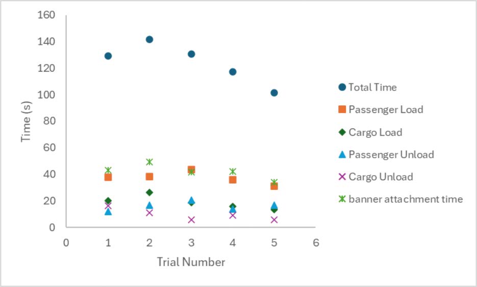
The time for each of these phases are added together. A more efficient and practiced individual will complete the ground mission. The chart below shows some time trials for the ground mission. With more practice with each component, the ground mission time was being done faster.
Conclusions
The aircraft, although yet to complete a successful test-flight, is theoretically able to complete all the designated missions. Given more optimization time and physical flight time, this aircraft would be a successful competition aircraft.
For the future, it is recommended to do more simulation and theoretical analysis before building an aircraft. That way, there will be a solid baseline to compare actual performance with. This design needs refinement of flight handling characteristics so that unloaded and loaded flight handle as similarly as possible.
As a team, we learned critical engineering lessons. Regarding aircraft design, we learned how to approach an aircraft design with mission requirements first and foremost. We also learned that every component effects all other components in a complex system. As a large team, we also learned the importance of a robust reporting and management structure.