Boeing Ergonomic Vertical Fin Fastener Installation Tool
Team: Boston John, Jay McNeill, Ryland Price, Brigham Radmall and Parker Hicks
Project Description

Boeing 787 Dreamliner
Boeing Salt Lake City assembles the vertical stabilizer for the 787 Dreamliner, where mechanics must crawl inside narrow bays and support a heavy hydraulic Huck tool at arm's length to install fasteners. Our team designed an ergonomic extension tool that allows mechanics to install Huck bolts from outside the bay, reducing fatigue and injury risk.

Mechanic crawling into bay

Huck Bolt Installation Tool

3D model of the vertical stabilizer
Performance Review
Performance was verified through visual surface inspection, static force analysis of the handle, grip force calculations using published strength data, and hands-on testing with Boeing mechanics at the Salt Lake City facility
| Requirement | Target | Threshold | Performance | Performance |
| Changes in Surface Finish | No Change | No Change | No Change | No Change |
| Load on Mechanic | 0 lbs | 3 lbs | 1.37 lbs | TBD |
| Set-up Time per Bay | < 1 min | 5 min | 30 sec | 20 sec |
| Total Fastener Installation Time in Bay | 5 min | 10 min | 7.75 min | TBD |
Design Description
The system consists of three subsystems: a load-distributing Baseplate, a guided Tool Support, and a Control Handle connected through steel conduit, cables, and an adjustable hinge.
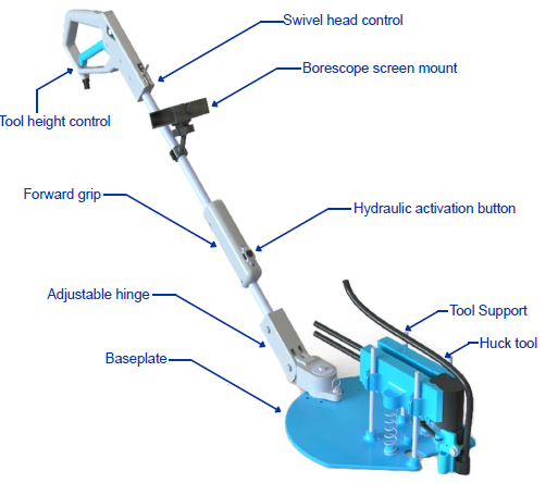
Complete tool assembly
Cable Actuation
Steel cables (similar to bicycle brakes) run along the conduit to control tool height and swivel head angle from the handle, eliminating the need for electronic activation methods.

Handle
Borescope Feedback
A camera mounted on the baseplate displays a live view to a screen near the handle, letting the operator see fastener alignment inside the bay.

Borescope screen mount
Surface Protection
An acrylic sheet placed in the bay prevents contact between the tool and delicate composite stringers. PLA Tough+ filament was selected for all 3D-printed parts.

Baseplate testing with acrylic sheet
Key Design Features
Baseplate
3D-printed platform that distributes tool weight across the bay surface. Includes a borescope camera mount and rests on an acrylic protective sheet to prevent composite damage.

Baseplate
Tool Support
Spring-loaded cradle that holds the Huck tool on machined guide rods with linear bearings for smooth vertical travel. A cable-driven collar controls the swivel head angle, and laser indicators aid alignment with Huck bolts.

Tool Support
Control Handle
Steel conduit handle with a cable-driven trigger for raising/lowering the tool, a three-position bolt for swivel head control, a forward grip with hydraulic activation button, and a borescope screen. A hinge allows height adjustment for different operators.

Control Handle
Conclusion
- The design meets all testable requirements and falls within threshold values for operator load and setup time.
- Key lesson: 3D-printed sliding interfaces caused binding. Switching to machined rods and linear bearings dramatically improved performance.
- Future work: develop a complementary tool for placing collar nuts prior to installation, further reducing the need to reach into the bay.
Special thanks to:
Forrest Newton, John Tran, Eric Hinckley, and Devon Wickham at Boeing in Salt Lake City.
Professor Graham at Utah State University