
Knee Subsystem
The purpose of this subsystem is to create a point of contact between the dummy and the rest of the system. A metal tube is strapped onto the dummy’s legs, and the rope connects through holes on either end of the tube.
Team: Taylor Torgerson
The Autoliv company wants to continue to improve airbag systems for use in vehicles. To continue their innovation, Autoliv requires more accurate testing technology for improvements. They have created a testing setup, with a sled and a human model. This setup mimics the front compartment of a car during a crash to test potential chest airbags. The setup currently only includes a chest airbag, which differs from reality because modern cars have several other airbags. The absence of additional airbags causes test inaccuracies.
Autoliv wants to improve the accuracy of a linear sled crash test for chest airbags by including a knee airbag. Cost constraints prevent Autoliv from using a real knee airbag in every crash test. The team was tasked with creating a system that limits lower body motion in the same way a real knee airbag would during the crash test.

| Requirement / Constraint / Goal | Target | Threshold | Predicted Performance | Actual Performance |
|---|---|---|---|---|
| Test-to-Test Pelvis Travel Distance | N/A | 5 mm | 5 mm* | 3 mm |
| Available Restrained Pelvis Travel Distance | N/A | 50–250 mm | 50–250 mm* | 100–200 mm |
| Available Free Pelvis Travel Distance | N/A | 0–100 mm | 0–100 mm* | 100 mm |
| System Tunability | 10 mm increments | 50 mm increments | 10 mm increments* | 10 mm |
| System Compatibility | Fit any PAB LAT Fixtures | Fit 2 PAB LAT Fixtures | Fit any PAB LAT Fixtures | ** |
| Subsystem Individual Weight | 50 lb | 100 lb | 30 lb | ~40 lb |
| Reusability | 300 tests | 100 tests | 300 tests* | 300 tests* |
| Initial Leg Angle Range | N/A | 25–70° | 25–70° | 25–70° |
| Tibia Restraint Angle | 90° | 90° ± 10° | 90° ± 10° | 90° ± 10° |
| Test Dummy Compatibility | Fit with 5th, 50th, 95th percentile test dummies | Fit with 5th, 50th percentile test dummies | Fit with 5th, 50th, 95th percentile test dummies | Fit with 5th, 50th, 95th percentile test dummies |
| Consumable Price Per Test | $20 | $200 | $30 | $20 |
* Indicates an estimate.
** System was not completed in time to measure actual performance.
The restraint system is composed of four subsystems: the damper, pivot, knee, and rope. As the linear sled test is run, a “crash” occurs and the dummy lurches forward. As the dummy moves forward, the knee subsystem is pulled forward. The rope gets loaded in tension and transfers the force back towards the damper. The pivot system directs the loading, and the damper dissipates the impact energy by deforming a metal sample.
The purpose of this subsystem is to create a point of contact between the dummy and the rest of the system. A metal tube is strapped onto the dummy’s legs, and the rope connects through holes on either end of the tube.

The purpose of this subsystem is to change the direction of the rope, allowing it to be pulled at 90 degrees to the dummy’s tibia and level with the damper.

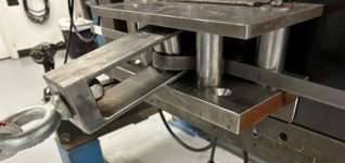
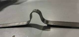
The purpose of this subsystem is to deform a metal sample as the center slider is pulled forward. This deformation creates the restraint that decelerates the dummy’s lower body.

The purpose of this subsystem is to transfer the energy from the dummy’s movement to the damper.
Once the system design had been completed, the team selected a variety of metal bar samples with varying heights and thicknesses. Three rounds of impact testing were performed to evaluate the sample performance under different speeds.


The sample deformation and restraint distance test data was compiled, and correlations were used to create a test matrix. The matrix will inform technicians of the required sample for a linear sled test given a desired speed, dummy size, and restraint distance.

The design met most of the requirements, though additional testing and analysis are needed to confirm compliance with the remaining criteria. This project showed that consistent communication, early feasibility checks, and expert input are critical for a successful design. The team learned that iteration and testing are necessary, and that interpreting data often requires outside guidance. The team’s design showed that restraining the dummy from behind is a viable option. Future work should focus on expanded testing with varied sample designs, improving system geometry for better fit and performance, exploring more effective cable materials, and redesigning the knee subsystem for greater durability and compatibility.
Special Thanks to Aaron Treglown at Autoliv.