Transfer Track Locking Mechanism
Team: Adrianna Harris, Hunter Nelson, Addison Collard, Zachary Heer, and Tyler Cook
Sponsor: S&S Worldwide
Project Description
Roller coasters with multiple trains or modular layouts often rely on transfer tracks and switch tracks to manage train storage, maintenance, or routing. These specialized track segments must align precisely and securely with the main coaster rails to ensure safe and efficient train movement.
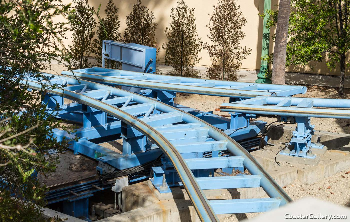
However, the connection between these track sections poses a critical safetychallenge: if the rails are not properly locked in place, misalignment or separationcan occur, leading to potential derailments or system failure. The problem is todesign a robust locking mechanism that can securely, reliably, and quickly connectthe moving rail segments of a transfer or switch track to the fixed coaster track,ensuring both structural integrity and operational safety during high-speed, high-load operation.
Our Design
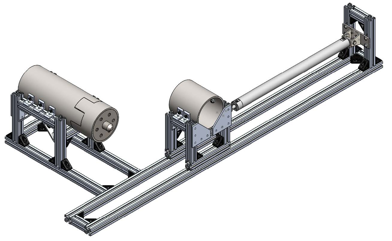
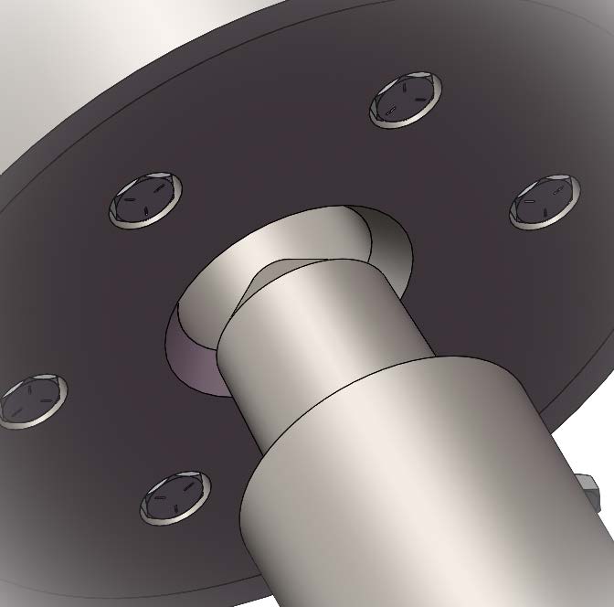
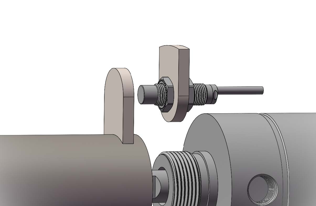
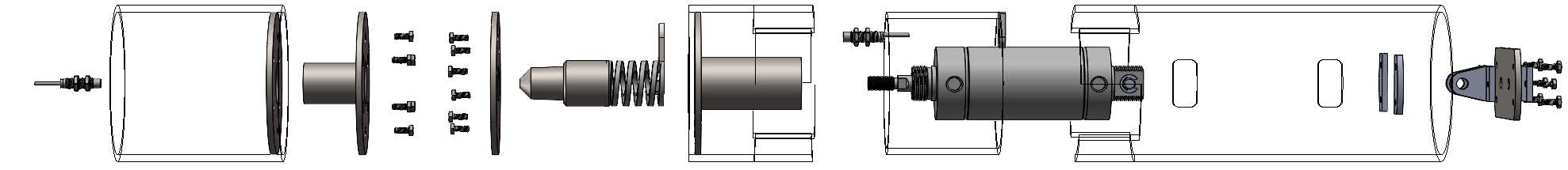
Our design utilizes a pneumatically actuated pin that extends concentrically into the center of the adjacent track rail. The pin locks the rail laterally while the force from the pneumatic cylinder locks it axially.

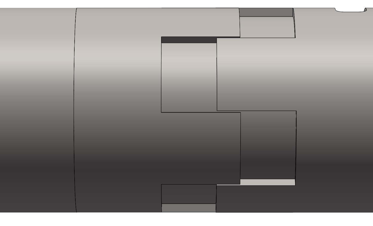
A section of the rail moves with the pin, interwoven using a teeth pattern. The teeth separate partially, leaving contact points that allow the train wheels to pass without “hopping” any gap between rails and reducing damage to the wheels.
The head of the pin and the face of the pin-receiving rail are tapered. This allows the pin to hit the rail face and push itself into alignment. While the pin aligns itself, the activation lateral tolerance is minimized.
Sensors are placed in the pinreceiving rail and behind the teeth-extending rail section to detect if the pin is engaged or disengaged.
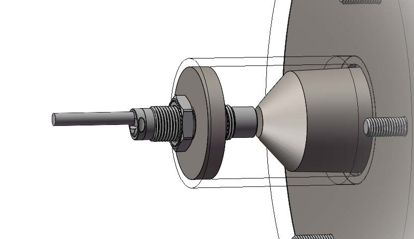
The pin is supported with a die spring. The spring cushions the pin to reduce damage to the face of the pin and rail when they collide.
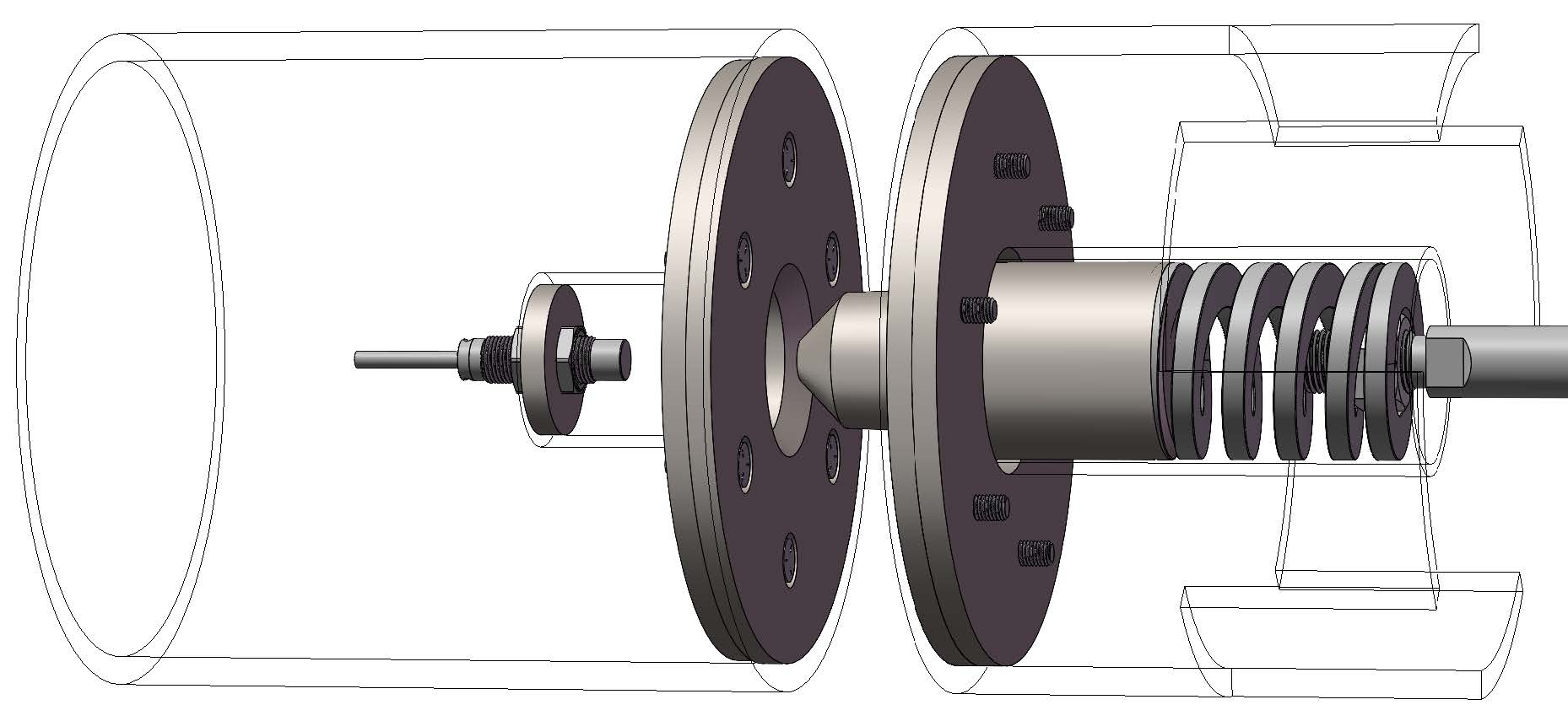
This design can be disassembled fully. To create a design that can disassemble, removeable plates and housing tubes are secured into the rail interior using bolts, nuts, and washers.
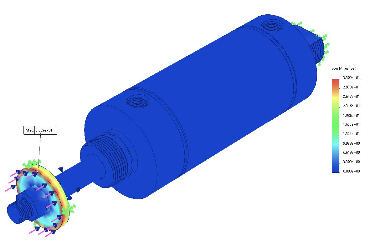
Stress Analysis of Washer
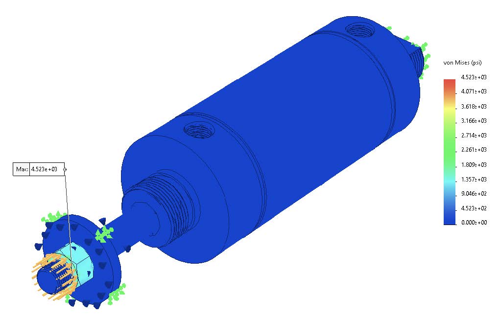
Stress Analysis of Nut
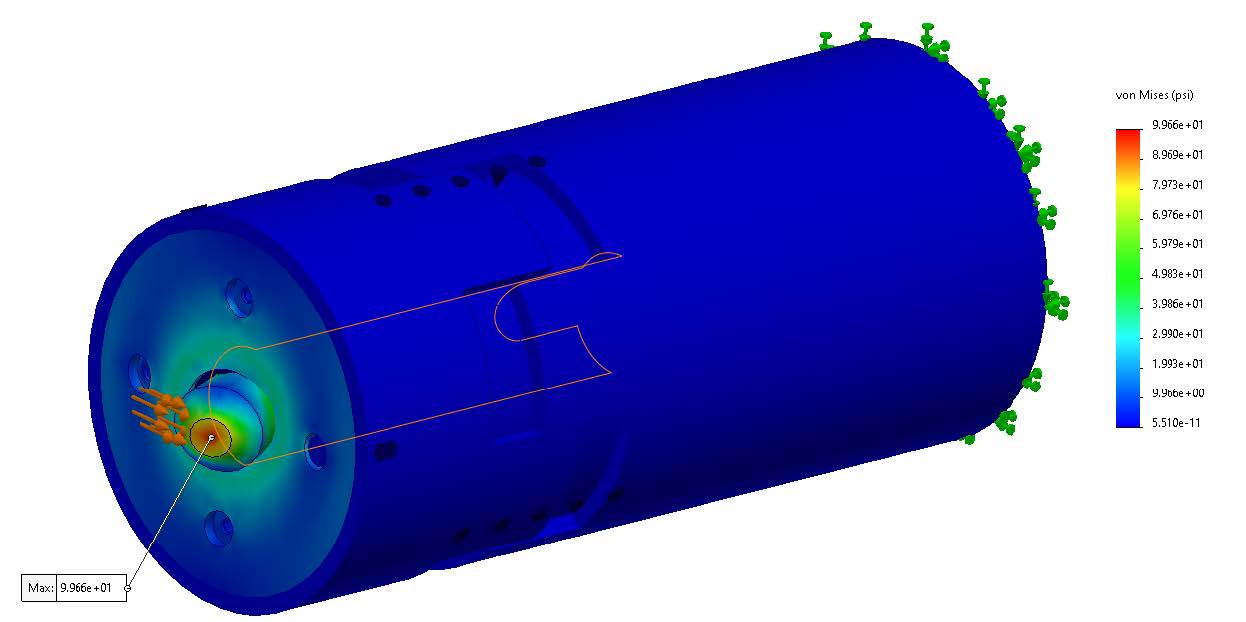
Friction Life Cycle Analysis
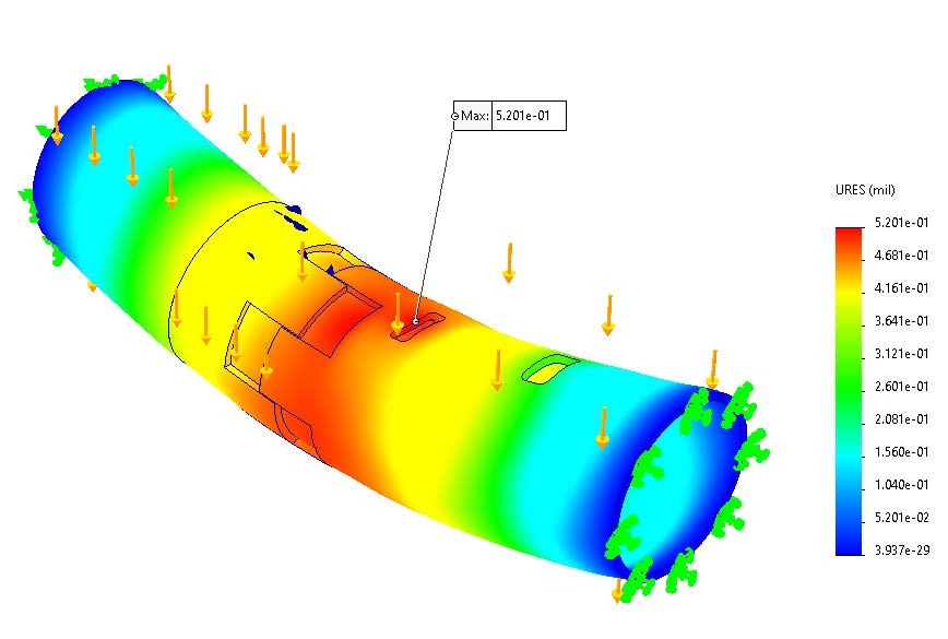
Max Allowable Load Analysis
Performance Review
| Requirement/Constraint | Description | Target | Threshold | Performance |
|---|---|---|---|---|
| Locking Speed | Time to securely lock tracks | < 1 second | < 2 seconds | 0.1083 seconds |
| Axial Track Distance | Distance between connecting rail faces when locked | 0 in. | 1/8 in. | 0.19 in |
| Final Lateral Tolerance | Lateral distance from alignment when locked | N/A | < 0.030 in. | 0.041 in. |
| Activation Lateral Tolerance | Lateral distance at which locking can engage | > ¾ in. | > 1/2 in. | 0.45 in. |
| Locking Life Cycle | Fatigue life of mechanism due to repeated locking | N/A | > 4.5 million cycles | infinite |
| Friction Life Cycle | Fatigue life of mechanism due to collision of components | N/A | > 4.5 million cycles | infinite |
| Max Allowable Load | Load that the mechanism can stay securely locked at | N/A | 44,000 lb. | > 44,000 lb. |
Conclusion
The final design successfully met most requirements and constraints, achieving fast locking speeds, minimal axial gap, and high load capacity, although slight deviations in lateral tolerance were noted due to fabrication limitations. During design and manufacturing we learned the critical importance of precision manufacturing, the need for robust test setups to accurately simulate real world conditions, and the need for early flexibility in design adjustments. For future work, we recommend improving fabrication precision, reinforcing the test structure to better mimic operational environments, and integrating automatic pneumatic control to stop motion upon lock engagement, further enhancing system reliability.