Nucor Roll Ring/Mandrel Loading Device
Team: Alex Allgrunn, Trevor Bryan, Kameron Crafts, Bryan Gricius, Jairus Larsen, and Taylor Lyon
Sponsor: Nucor
Project Description
- Safety is a top priority at NUCOR. In an effort to mitigate and eliminate hazards, NUCOR is trying to automate and redefine everyday tasks that expose teammates to risks and hazards, along with making their job easier. Teammates are no longer allowed to touch any load that is suspended from a crane with their hands because of the hazards associated with them. Teammates are struggling to load roll rings onto a mandrel without using their hands.
- Nucor asked the team to design a one-man-operable device that can load the roll rings onto the shoe that safely holds the roll ring. Then, a technician is able to push the roll rings onto the mandrel instead of using a crane and push rod.

Primary Requirements:
- No hydraulics
- Lift up to 1250-lb rings
- Fit in a 5 ft. x 15 ft. area
- Loading process should be quicker
- Teammates cannot handle suspended loads
Design Description

Top Level Assembly
The devicepermits safe and efficientmounting ofroll rings onto each side of the mandrel.The design incorporates electrical controls for remote operation

Mandrel Stand
The mandrel stand clamps the mandrel in place during loading and unloading of the roll rings.

Cart & Shoe
The cart and shoe supports roll rings as a technician uses electrical controls toalign the roll ring with the mandrel.
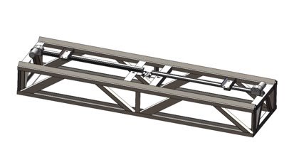
Base Frame
The base frame is the main structural component of the device. Rails on the frame allow for cart rolling and linear actuator mounting.
Performance Review
The team verified the performance of the device per the requirements with three methods:
- Full Functional Testing: Tests all configurations and functions of the device.
- Timed Testing: Tests if the device can be loaded within the timing requirements.
- Inspection Checklist: Verifies that inspection-based requirements are met.
| Requirement | Target | Threshold | Predicted | Actual |
|---|---|---|---|---|
| The loader footprint shall fit within the designated space | 3 ft by 8.5 ft | 5 ft by 15 ft | 3 ft by 8.5 ft | 2.4 ft by 8.9 ft |
| The vertical height of the loader shall be constrained to an ergonomic height for the user | 4 ft | 5 ft | 4 ft | 4 ft |
| The technician shall be able to load the roll ring onto mandrel from shoe quickly | 3 min | 4 min | 3 min | TBD |
| The technician shall be able to load the ring onto shoe from crane quickly | 1 min | 2 min | 30 s | TBD |
| The loader shall lift the heaviest roll ring | n/a | 1250 lb. | 1250 lb. | TBD |
| The loader shall have a vertical travel distance that encompasses all ring sizes with additional space | 10 in. | 7 in. | 11.75 in. | ~10 in. |
| The loader shall have an axial travel distance that encompasses the length of the mandrel with additional space on either side | 3 in. | 2 in. | 3.5 in. | TBD |
| The loader shall have sufficient axial travel distance to load roll rings onto the mandrel | 28 in. | 14.25 in. | 25.5 in. | TBD |
| The mandrel shall have movement in the pitch & yaw directions | ±1° | ±0.5° | ±1° | TBD |
| The loader shall accommodate all roll ring sizes | n/a | 3 | 3 | 3 |
| The diameter of the backstop shall be sufficient to push the roll ring onto the mandrel | 1 in | 0.75 in. | 1 in | 1 in. |
| The device shall have sufficient axial force to push the roll ring onto the mandrel | 150 lb | 80 lb | 150 lb | TBD |
Conclusion

- Structure was manufactured well, very close to designed
- Device passed testing
Future work:
- Design integrated control system