
Unmanned Aerial Vehicle Sensor Deployment Mechanism for Idaho National Lab – Senior Capstone Design
Team: Garrett Oliekan, Alan Petersen, Ethan Ellsworth, Thomas Payne, Jacob Quayle
Sponsor: Idaho National Laboratory
Project Description
Utah State University’s Aggie Altitude team is collaborating with Idaho National Lab to develop a Sensor Deployment Mechanism for use in a T 20 Arcturus UAV
Idaho National Laboratory uses the Arcturus T 20 unmanned aerial vehicle to field test different sensor systems for customers The T 20 does not have landing gear and, therefore, it takes off and lands on the belly of the aircraft To prevent damage to the sensor systems, the sensors are stored inside the body of the UAV and deployed once the aircraft is in the air The mechanism that deploys the sensors after takeoff also needs to be able to retract before landing In the past, the mechanism currently employed by INL has been unreliable
Aggie Altitude has been tasked with creating a design that improves the reliability of the sensor deployment mechanism while minimizing power draw and weight Such a design should also include easy maintenance and adaptability for exchanging different customer sensory systems Successfully redesigning the sensor deployment mechanism will provide INL with increased revenue over time along with lower costs and time associated with maintenance of the system
Project Introduction and Preliminary Concept Generation
Problem Objective: The T 20 payload bay is accessible from the bottom of the aircraft The T 20 does not use landing gear but rather is recovered by “belly landing” It is necessary to retract the payload into the aircraft during launch and recovery During flight and data collection the payload is deployed from within the aircraft with a Sensor Deployment Mechanism ( and must be isolated from the landing surface during recovery This is currently accomplished by doors that open during flight The existing SDM is unreliable INL is seeking a more robust and reliable solution for the SDM and payload doors
Major Functional Requirements:
- System must be reliable 500 MTBF), repeatable (within 015 and mount to airframe fuselage
- System shall be less than 13 5 pounds and fit within a 11 X 24 X 9 size envelope
- System shall operate on 12 or 24 Vdc and have single power connection from UAV
- System shall not introduce any electrical “ that would interfere with autopilot or communication devices
- System shall be activated by an autopilot commanded voltage and therefore shall have the required electronic control mechanism to operate when that voltage is received
Deliverables: Prepare and submit P reliminary Design for review and concurrence by INL Preliminary Design package shall include design drawings, schematics, matrix indicating performance of design in meeting requirements, design limitations, design risks and discussion of the decision processes and criteria Prepare and submit the Final Design for review and concurrence by INL The Final Design package shall include final design drawings, schematics, fabrication recommendations, material list, test plan, interface documents, notional operational instructions, and analysis documentation
Project Kick off Our team had the opportunity to go to INL in person and meet with our sponsor We spent a whole day at the field office observing and learning as the engineers/technicians worked on a few UAV’s During that time, we had the opportunity to generate about a 12 different concept sketches to be analyzed in more detail later
Preliminary Design and 1st Proof of Concept
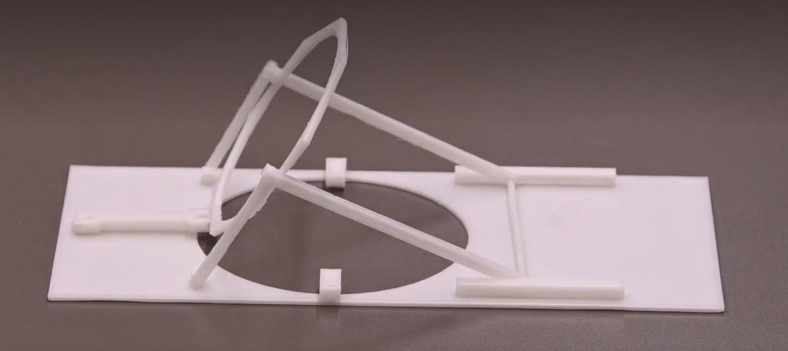
The first design, termed the "A frame" design, featured a pair of rails and linkages to lift and lower the sensor The model was very roughly 3 D printed to gauge if this concept was worth pursuing.
The initial design featured two flexible A frames on a sliding rail that supported most of the weight of the sensor, and a third linkage in the back that supported the orientation of the sensor and guided the sensor as it was being deployed and retracted A large disk in the middle served as a sensor mounting plate The 3 D print was functional, but very fragile As such, a second, full scale model of the design concept was printed This time, a sensor model was included to show that similar sensor geometries could be well managed by our design
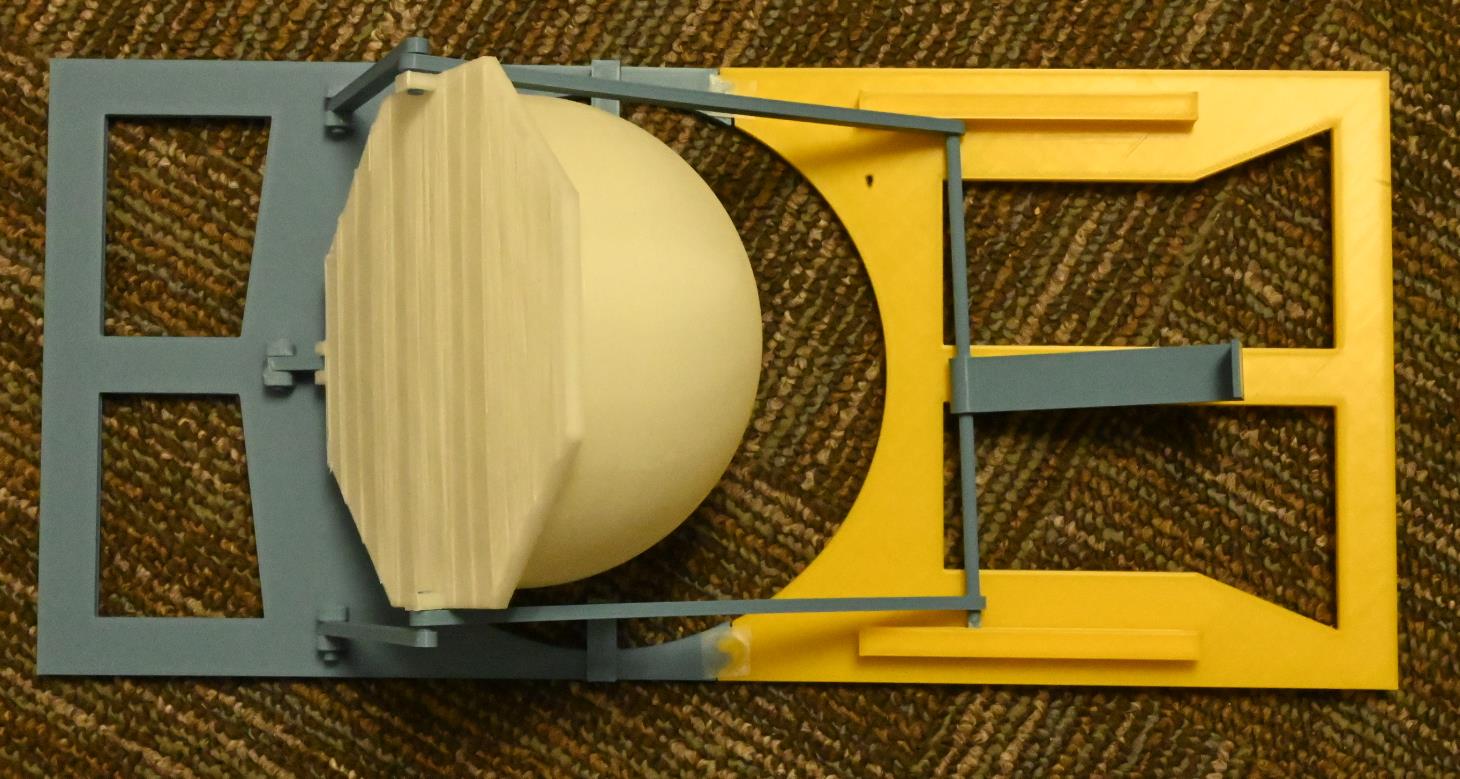
Preliminary Design Review
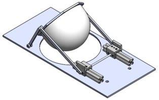
The current design features a more robust rail system Instead of a rod sliding in a slot, as featured in the preliminary design and 1 st proof of concept, two 80 20 extruded aluminum rails have been selected, with accompanying slider bearings The sliders are then connected in the middle to provide support The original design had so many hinge points that were relatively weak such that a large amount of unwanted twisting and bending was induced We also started planning for a bay door design and accompanying features to mount motors and control panels The maximum sensor size envelope was also included in the solid model to verify range of motion
Critical Design Review
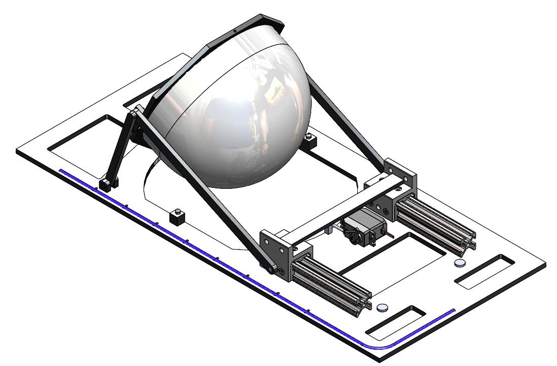
The design for CDR consists mainly of changes made to the locking pin mechanism, cable routing features, more robust rails, alignment pins, and a door mechanism Cable management features were added to route any wiring necessary for electronics away from the moving components of the SDM The locking pin and alignment pins were added to ensure the alignment of the sensor in its deployed position, as well as lock the sensor in place while deployed The door mechanism was included as a method of opening and closing the UAV bay doors during operation, but the design only consisted of the same door opening assembly currently in operation
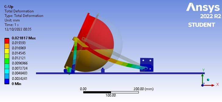
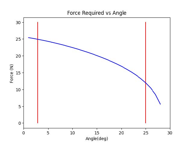
A Finite Element Analysis ( was performed to verify rigidity and displacement of the SDM and the all the moveable components This also includes an analysis to verify that the SDM can withstand the loads required and that the sensor will not induce any unreasonable twisting or distortion A force analysis was also performed to determine the maximum sensor weight that can be supported by our SDM as well as the force required to both retract and deploy the sensor
The motor that was purchased is not back drivable, but we learned a lot while assembling the screw/motor assembly From this video we learned the motor could drive the power screw and that the custom designed nut would function the way we intended We learned that we would need something between the aluminum plate and the nut to reduce friction as the motor drives the nut back and forth
Major Design Decisions
- We decided to change from a two rail system to have everything on one side of the mechanism.
- We designed a power screw assembly to drive the motion of the sensor using a system of linkages.
- We discovered the need for a motor that is back drivable This allows for the emergency close to function
Power Screw Assembly: Proof of concept
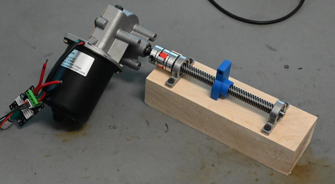
The motor that was purchased is not back drivable, but we learned a lot while assembling the screw/motor assembly From this video we learned the motor could drive the power screw and that the custom designed nut would function the way we intended We learned that we would need something between the aluminum plate and the nut to reduce friction as the motor drives the nut back and forth
Final SDM Design Prototype and Drawing Package

The final design consists of a power screw assembly that drives a lever system to deploy and retract the sensor An interchangeable 40 lbf gas piston drives the retracting motion (and serves as an emergency close feature in case of power outage) and the 6 N m back drivable servo motor both powers the deployment and controls the retraction

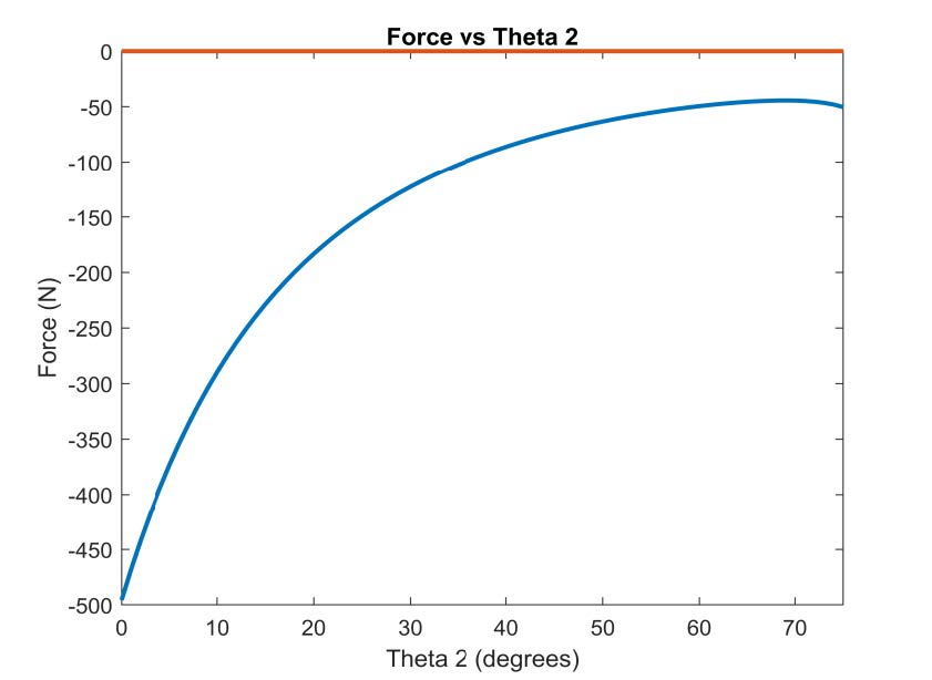
The entire system (without bay doors and locking pin mechanism) weighs 10 9 lbf and can support a maximum sensor weight of 14 8 lbf and has a maximum size envelope of 11 x 24 x 9 The design is not yet optimized for mass savings but has been verified to meet all functional requirements An additional force analysis was included to ensure that the piston and motor were providing enough force for the required sensor weight The analysis concluded that a 28 lbf piston was required If a 40 lbf piston is used in the assembly, the required motor torque is 4 4 N m Both results validate the decisions for the selected components
A Brass nut with a steel flange was also added to replace the 3 D printed nut for strength and durability The machined brass nut also limits the tilting and play in the nut on the screw assembly
Lessons Learned
Keep it simple Simplifying the design is one of the largest factors for most of our major design decisions More complexity introduces more occasion for failure and misalignment
Design for Manufacturability It is easy to make " solid models of a part and to make assemblies look great in software, but it is more important to consider how the part is going to manufactured and who is going to assemble it
Consistency A similar lesson learned is in keeping things consistent Consistent thicknesses, consistent fastener sizes, consistent fillets/rounds, etc make the overall process simpler and make off the shelf parts more accessible
Recommendations for Future Work
- Design a housing for the power screw assembly to prevent dust and debris from entering, to the extent possible
- Cut weight where possible to lighten the assembly
- Design specific wire routing features to keep everything organized inside the UAV and protect cables from harm due to moving parts
- Design the features to attach the sensor to the sensor plate
- Design the features to attach the deployment mechanism to the UAV
- Integrate the locking pin and door mechanisms to the current design