INL - Building Automation Sector Model
Team: Josh Hansen, Myles Bradley, Jared Leary
Sponsor: Idaho National Laboratory
Project Description
The Idaho National Laboratory has a division that researches cyber security risks with the aid of scale, fully function models. This division is called CELR, and they are looking to expand the models and scenarios that they can test, which includes a hospital room.
- Build a system utilizing a prebuilt VAV box that can simulate positive/negative air pressure in a contained environment.
- This system must be small enough to be carried around and displayed at events.

General layout of final system
What We Learned
Overall, the design met the basic requirements and constraints. The project is easily carried by two people and can fit on a table. Furthermore, the model room reaches positive and negative pressures that are typical for a hospital room. The pressure range would likely be improved by additional calibration.
As mechanical engineers, we had to learn how to properly wire electronics and order the right parts. These lessons had to be learned to not burn out any components. There were many times where we double checked our design decisions which saved us both money and time.
For future work on this project, we would rework how the ducting would fit together and design an electrical cabinet from scratch. These changes would allow the creation of a cleaner design and could potentially decrease the size of the system. We would also dedicate more time to further refine user interface on the HMI.
Requirements and Constraints with their related Target, Threshold, and actual Performance values.
| Requirement/Constraint | Tested Values | Target | Threshold | Performance |
|---|---|---|---|---|
| Simulate positive and negative pressure | Steady-State Pressure difference (in.H2O) | <=±0.25 | >±0.25 | -0.030 to 0.170 |
| Accurate Pressure measurement | Resolution of Pressure Measurements (in.H20) | 0.001 | 0.01 | 0.005 |
| Light enough to be lifted by 2 people or less | System Weight (lb) | 70 | 100 | ~80 |
| Fit on a table | System Base Area (ft x ft) | 2’x4’ | 3’x4’ | 1.43’x2.98’ |
| System must be responsive | Input Response Time (s) | 1 | 2 | 1.832 |
CFD Analysis
CFD Analysis was used to determine the effectiveness of the design to create a working range of pressure values.
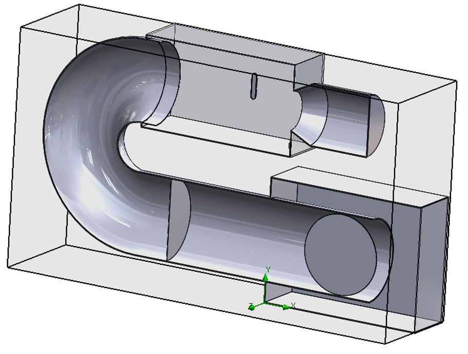
Geometry for CFD simulation

CFD results of in.H2O vs Damper angle. This test was run for multiple fan curves.