Demonstration Motion Table Development
Team: Alan Christenson, Ryan Cook, Brandon Davidson, Dylan Petersen, Joseph Randall, and Jason Ripley
Project
Project Description L3Harris uses motion tables to test their antennae. They require a small prototype model motion table for demonstrations with clients and future employees. A motion table can move in six degrees of freedom: roll, pitch, yaw, heave, surge, and sway. The Catalyst Engineering Design Group re-engineered a prototype table-top version of a motion table that can be run using a Python GUI on a laptop.
Project Requirements
- 0.1 degrees to a waveform at 1 rad/s
- A simple user interface •25 degrees of roll, pitch, and yaw •4 in. deflection of heave, surge, and sway
- 3 in. sinusoid of heave, surge, and sway at 1 rad/s and accuracy of 0.01 in.
- Lift at least 10 lbs.
Performance Review
We used a digital protractor to measure roll and pitch of the table. We measured and meet the accuracy requirements in roll and are close in Z. We could not get a measurement method with accurate enough resolution to measure yaw. Our linear deflection and angular displacement meet the requirements; however, we could not reach the desired accuracy. Our average error for each measurement is as follows:
- Roll: 0.08 degrees
- Pitch: 0.113 degrees
- X: 0.08 inches
- Y: 0.06 inches
- Z: 0.014 inches
Design
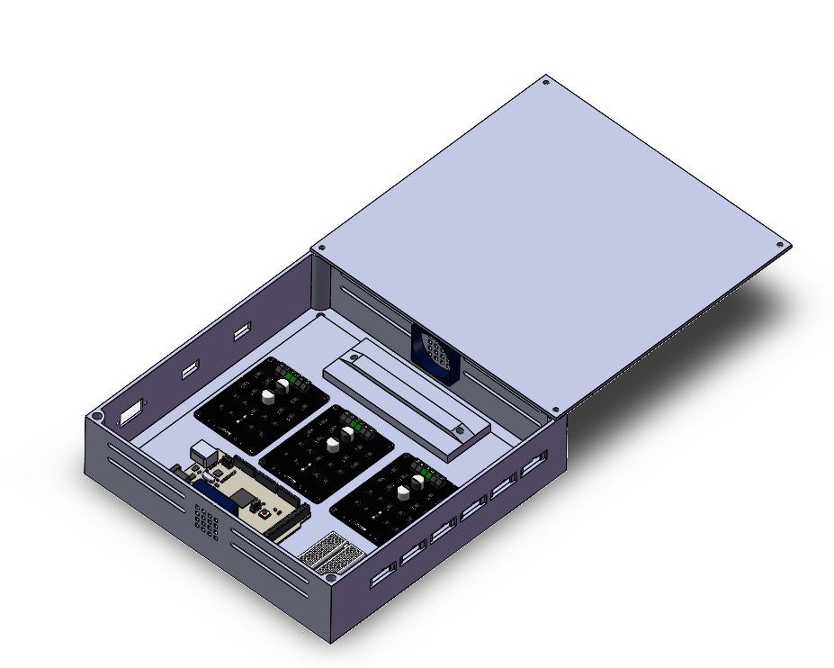
Fig. 1 Rendering of Wire Enclosure
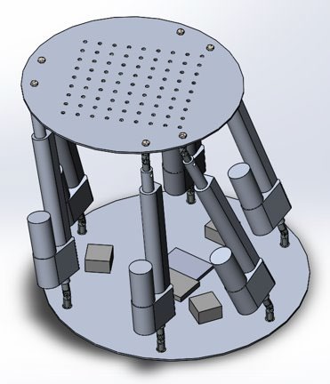
Fig. 2 Rendering of Stewart Platform
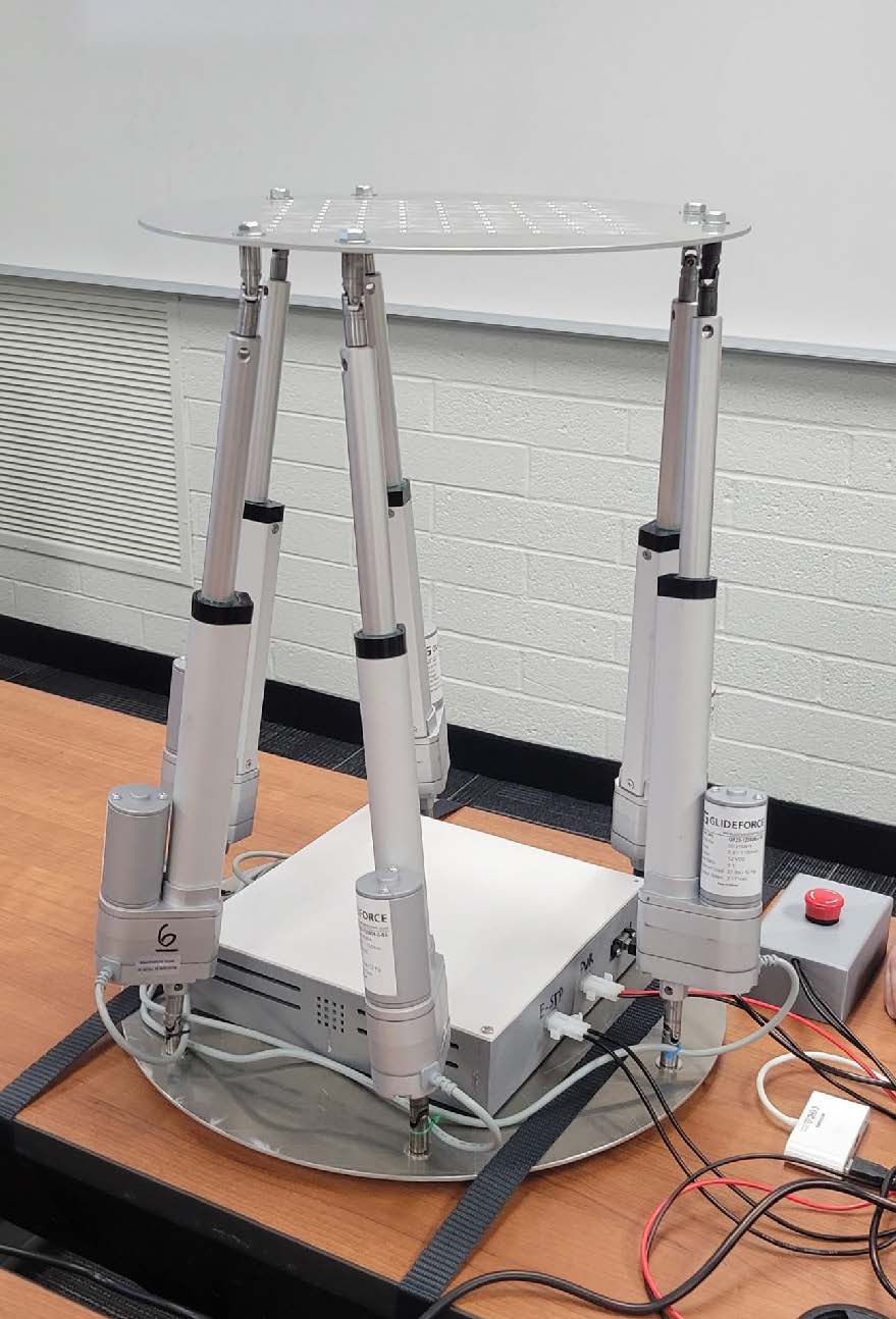
Fig. 3 Finished Demonstration Table
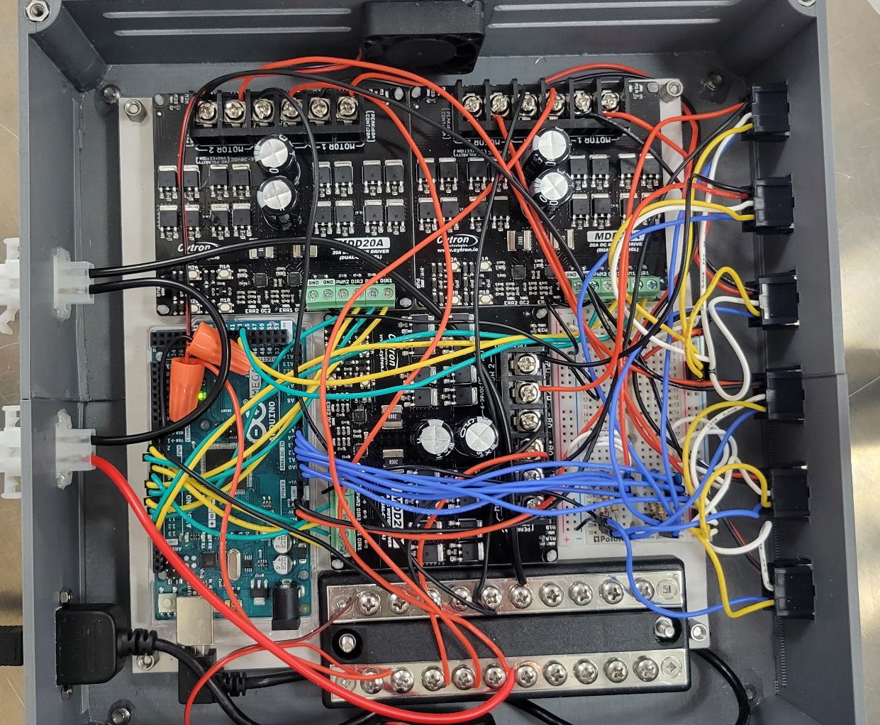
Fig. 4 Wire Enclosure

Fig. 5 Box Diagram of Electronic Subsystem
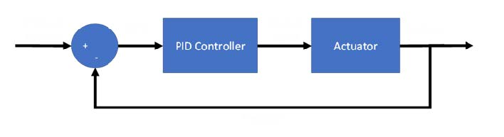
Fig. 6 Feedback Loop of Linear Actuators

Fig. 7 measuring deflection of translation motion

Fig. 8 Digital protractor to measure angle on table
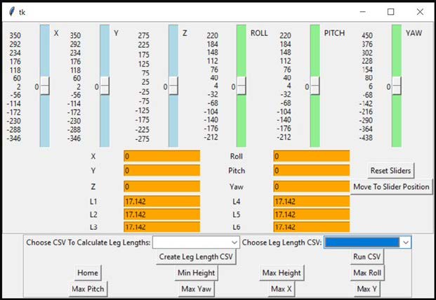
Fig. 9 GUI Model

Fig. 10 Team members
Conclusion
The table performance meets all the speed, translation, and angle requirements given by the client. There were changes that needed to be made with wiring components as well as fixing bugs in the code in order for the table to perform its proper functions.
Our design meets the requirements and constraints moving at 1 rad/s and 25 degrees of roll, pitch, and yaw. As mentioned there was no accurate way of measuring the yaw but according to the leg length values and other arguments output in the code we know we can reach the goal of 25 degrees in yaw. While measuring all the values in roll, pitch, X, Y, and Z we found the accuracy for each direction of movement are close but does not fully meet the threshold of 0.01 in accuracy.
Lessons Learned: Our team learned that we need to plan out and order parts as soon as possible. There were some issues receiving some ordered parts in a timely manner. We learned we need to pay attention more to specifications of electronic parts before ordering them. With our first prototype we had motor controllers that could not supply enough current and overheated thus leading us to get more robust motor controllers. We learned that we could have started coding the GUI and Arduino sooner as we ran into many bugs along the way we kept needing to fix.
Recommended Future Work: The case for wiring and housing for the E-stop could be upgraded to a stiffer material. When the actuators sometimes went to farther positions than they were supposed to parts of the wire housing snapped being made of brittle 3D printed plastic. Another addition would be adding blue Loctite to the connections of the joints, set screws, and bolts as those connections can come loose from time to time.
Thanks to L3Harris and Scott Lyon for sponsorship and mentorship.