Evaluating Timing Errors in AI Hardware Accelerators
Team: Andrew Chamberlin
Sponsor: USU Bridge Lab
Project Problem & Relevance
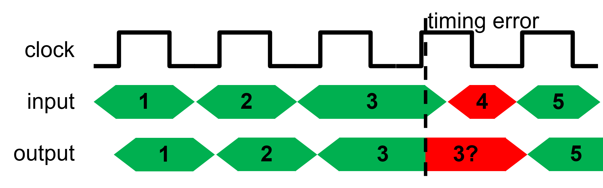
- Simulated timing errors are represented as random or as a single process.
- Both methods neglect the nature of timing errors in real circuits.
- Absolute worst-case simulated errors are too restrictive.
- Better than worst-case simulated errors leave room for flaws in the design.
- By emulating and characterizing timing errors, future research efforts will be able to model their simulated errors for more accurate testing.
System

Methods
- Design a Systolic Multiplier Array (SMA) with parameterized size in Verilog.
- Use AXI Interface protocols and a custom control scheme to move data between clock boundaries crossing.
- Develop software capable of interfacing with the AXI Interface.
- Test cross layer interactions to ensure the AXI Interface is correct and error free.
- Design method of over-clocking just the SMA logic to create timing errors.
- Create test structure for repeatable and customizable tests in the software with external UART interface.
- Create scripts on the host for generating test cases and communicating over UART.
Conclusion
- Natural circuit errors were found to be discrete and deterministic with small variance across multiple runs.
- Future research will include under-volting as an alternative source of creating timing errors as well as improving the complexity of testing and analysis.
- Small discrete sets of possible errors for a given controlled environment means that error detection and error correction should not assume that errors are equivalent to completely random outcomes.
- Project management is difficult and ensuring thorough designs up front saves a lot of time in future redesigns of the system.
- Next, we will expand the interface to include direct memory access between the PL and the PS, allowing for larger and faster transactions.