Expanding the Angle of Acceptance of a Polymer Optical Fiber
Team: Alia Dabb, Connor Patton, David Nielsen, Sophia Kokoshka, Emma Breck
Sponsor: Biomerics
I. Abstract
Goal
- Increase the angle of acceptance of a polymer optical fiber (POF) to be greater than the angle of acceptance of a more expensive light fiber (79 °°) at a reduced cost
Approach
- Modify the POF through:
- Mechanical splicing with ferrules and without)
- Ball end milling
- Creating a concave surface with UV adhesive and ball point pen tip
Results
- All modifications showed an increase in the angle of acceptance
- Ball end milling and a tip made from adhesive were the most promising modifications
II. Introduction
Most polymer light fibers on the market have a 60 angle of acceptance. Toray light fibers have up to a 79 angle of acceptance, but they are 20 times the cost of other light fibers [1]. This design aims to create a light fiber with the following characteristics:
- Angle of acceptance greater than 79
- Costs less to produce than Toray light fibers
- Diameter is 2.85 mm or less
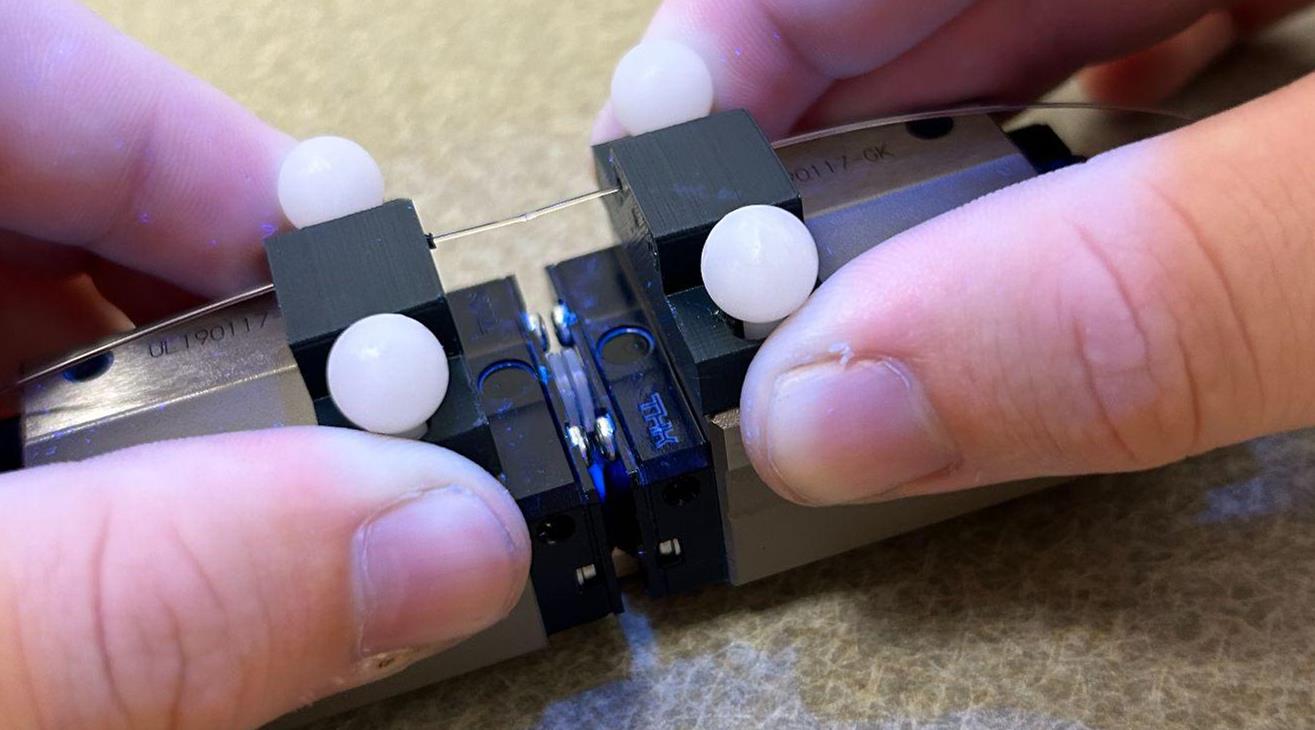
Figure 1. Rail line used to reduce human error while performing mechanical splicing without a ferrule.
III. Methods
Four different types of modifications to the light fibers were performed. These modifications were:
- Ball end milling
- Mechanical splicing with ferrules
- Mechanical splicing with adhesive
- Adding an adhesive lens to the fiber

Figure 2. Mechanical splicing process.
The ball end milling drilled a concave cavity at the end of the Eska light fibers (have standard angle of acceptance of 60 °°). The mechanical splicing attached a short segment of Toray fiber to a long section of Eska fiber using Loctite adhesive with the addition of ferrules for some attachments. The adhesive lens attaches a lens made of loctite modified with a ball point device to the end of an Eska fiber.
IV. Results
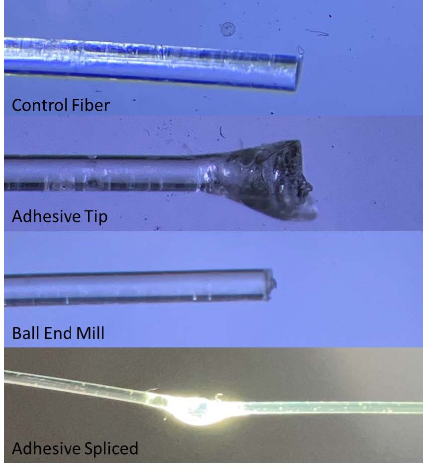
Figure 3. Images of the POFs of the prototypes.
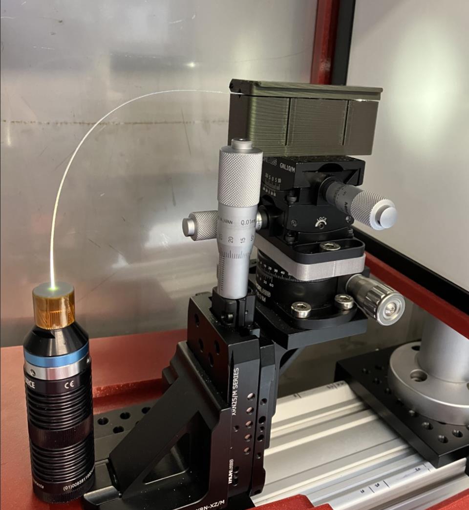
Figure 4. Method to find acceptance angle.
The second round of testing showed promising results for the adhesive tipped fibers. The ball end mill fibers performed similarly to the first round of testing.
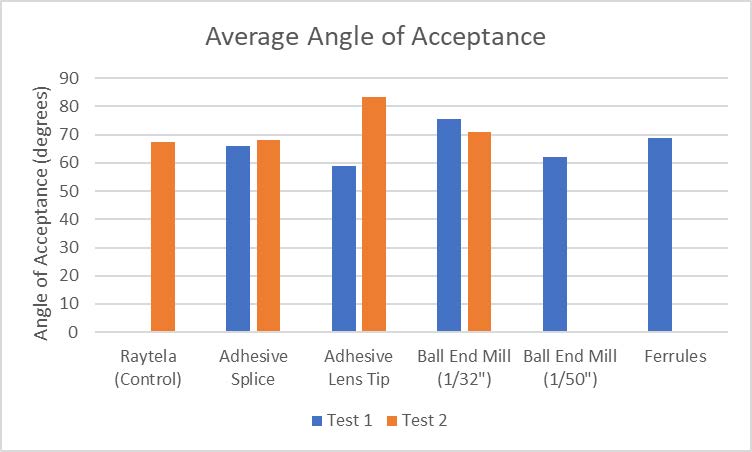
Figure 5. The average angle of acceptance from the two rounds of prototyping. A Toray fiber was used as a reference. *There was not sufficient data from the adhesive spliced fibers to take an average, as two spliced fibers failed.
V. Conclusions
From the results of the prototypes, we can determine that both ball end milling using a 1/32” tip and having a tip made from adhesive and shaped with a ballpoint pen produce the greatest acceptance angle on a modified fiber. Both lens types also performed better than Toray light fiber in testing.
VI. References
- Plastic Optical Fiber RAYTELA. [Internet]. Toray; 2020 [cited 2022 Oct.13]. https://www.electronics.toray/en/products/raytela/